2
\$\begingroup\$

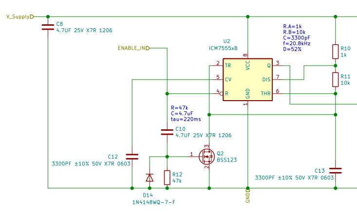
I have a ICM7555 with a 12 V supply in an astable circuit. When ENABLE goes high, I want my output to be high for a given amount of time, then carry on as a normal astable from there.

So I have a BSS123 pulling Trigger/Threshold low for a bit with an RC on the gate. The BSS123 portion of the circuit seems to do as I expect, pulling low for a time. The waveform of Trigger/Threshold seems to be as I expect, holding low for a time, then bouncing between 4 V and 8 V at 20 kHz.

But the output (pin 3) is not doing what I expect. Output is high, even before enable goes high, then stays high for the time that BSS123 is pulling low (which makes sense to me), then goes to a 20 kHz oscillation between 12 V and 11.7 V.

Is there something obvious I'm missing that's holding the output high, both before enable goes to 5 V and after the Trigger/Threshold node starts oscillating? Or is there a better way to achieve the output waveform I desire?

schematic

For some more context, what I'm trying to do is drive a solenoid. I want to give it full current for a time (while the BSS123 is conduction) and then ~50% afterwards. The output will be connected to a gate driver MCP1416, but it is not currently populated. The gate driver PWMs the gate of a BUK9608 controlling current to the solenoid.

\$\endgroup\$
0

3 Answers 3

1
\$\begingroup\$

The 20kHz oscillation hints at the whole thing working, but somehow the 555's output Q isn't making it all the way down to 0V.

I suspect that the problem is whatever you've connected to that output (Q, pin 3), not anything shown here. Or a broken 555 output driver.

EDIT:

I'm certain that it's oscillating, because you see the 4V to 8V excursions at the trigger/threshold. Because of this, I'm also certain that the output should also be oscillating between 0V and 12V even with a "heavy" load, like 1kΩ. Every element of the 555 is working as it should, except the output.

It's really easy to kill a 555 or its CMOS cousin, by overloading the output. The output can source or sink over 100mA, and with a 12V supply, that's well over 1W of power disspipation. This can fry one of those poor output transistors in short order. Just because the output is able to sink/source 100mA doesn't mean one should.

\$\endgroup\$
4
  • \$\begingroup\$ I thought the same thing, which is why I depopulated the component connected to Q/pin3. But there was no change in my measurements at Q. \$\endgroup\$
    – matth
    Commented Sep 10, 2021 at 12:15
  • \$\begingroup\$ Then I stick by my reasoning that the 555 output driver is damaged. If your trigger/threshold voltage is oscillating between 4V and 8V, there's no other reason (I can think of) why Q shouldn't flap up and down all the way. \$\endgroup\$ Commented Sep 10, 2021 at 13:14
  • \$\begingroup\$ I updated my answer to explain this. \$\endgroup\$ Commented Sep 10, 2021 at 13:34
  • \$\begingroup\$ I went back and replaced the chip this morning. You were exactly right, damaged part. \$\endgroup\$
    – matth
    Commented Sep 13, 2021 at 15:29
2
\$\begingroup\$

...then goes to a 20 kHz oscillation between 12 V and 11.7 V.

I think that then Q2 is slowly switching off. The combination of C10, R12 and D14 doesn't give a "hard" voltage to the gate of Q2 is it isn't switched on/off abruptly.

When Q2 is switching off but still in a high resistance state (so it can pull some current from C13) it will help to discharge C13 and then infuences the timing circuit around C13.

What I would do is add some CMOS logic gates to make a delay circuit and then hard-switch Q2 on/off.

\$\endgroup\$
1
  • \$\begingroup\$ I follow your logic, and that makes sense. But I would only expect that issue to persist for a few ms, not remain after many RC time constants. Using logic gates probably remains a good suggestion, though. \$\endgroup\$
    – matth
    Commented Sep 10, 2021 at 11:52
1
\$\begingroup\$

When power first is applied, C13 is completely discharged, forcing the output high. This is independent of the state of Q2.

You don't give us the Enable voltage in its low state. The 7555 datasheet says its typical threshold value is 0.75 V. If your Enable voltage is higher than this, the 555 will be trying to operate even when Enable is "low" enough to keep Q2 turned off.

\$\endgroup\$
1
  • \$\begingroup\$ About C13 starting discharged, that makes perfect sense, and I don't know why I didn't realize this before. The enable voltage in low state should be 0V, I measured at 40mV. \$\endgroup\$
    – matth
    Commented Sep 10, 2021 at 11:46

Your Answer

By clicking “Post Your Answer”, you agree to our terms of service and acknowledge you have read our privacy policy.

Not the answer you're looking for? Browse other questions tagged or ask your own question.