1
\$\begingroup\$

I've been testing a power supply I've made and noticed that a +/- VCC voltage spike occurs when a resistive load is attached/disconnected (or when a power is lost) due to capacitor transients.

The spikes are relatively short (around 1 millisecond.) I would like to eliminate them if possible on the power supply level.

The negative voltage spike could be eliminated by attaching a Schottky diode, which is probably the easiest solution, but is there a better one? Better yet, should I be worried at all?

I am tempted to design a sub-circuit that would monitor an abrupt change in voltage and, if detected, cut the load off for an arbitrary duration of time. Seems like overkill, though.

The regulator used is an LM7812 (100uF on the input and 33uF on the output) with a load that can draw up to 0.5A.

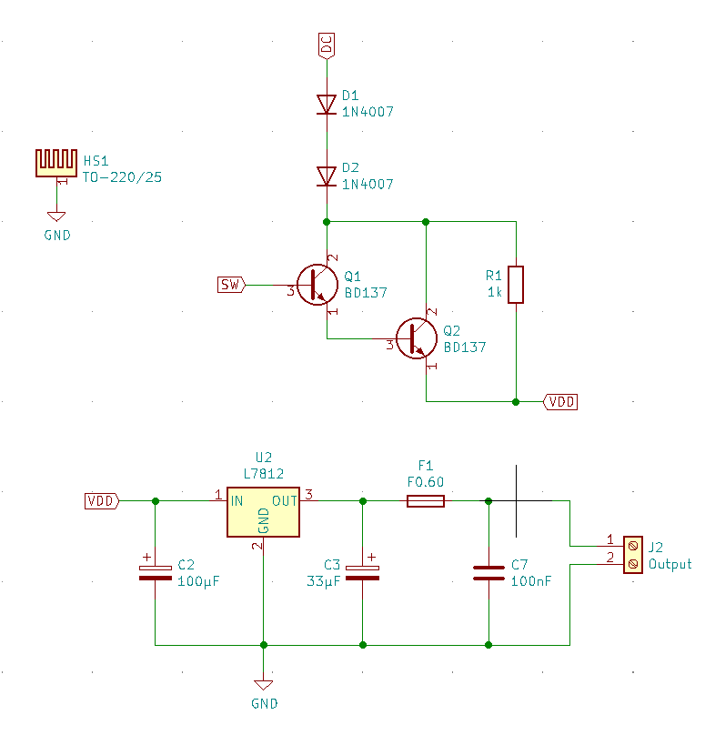
Circuit

Circuit

Old 19V laptop adapter is used, mostly because it was the only one I had lying around that was able to provide 2A of current needed for 4x 0.5A loads.

To get around the thermal limitations of LM7812, I used two rectifier diodes in series to drop around 2V and a Darlington pair to drop additional 2V.

Darlington pair is also used for preventing potentially high in-rush currents - comparator turns it on after ~250ms.

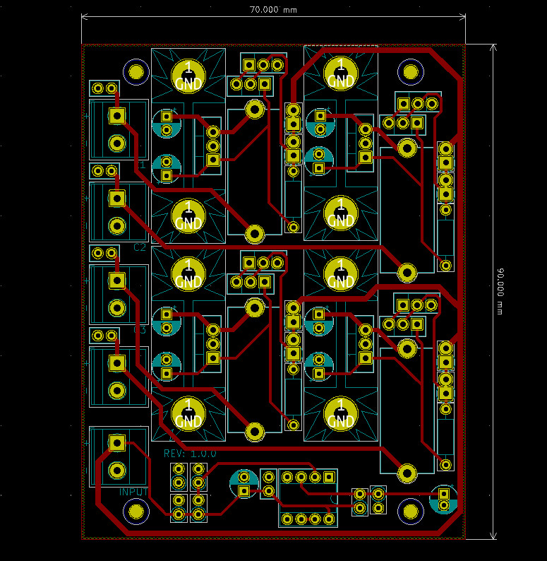
PCB

PCB

PCB is relatively simple.

Test

Test load was purely resisitive, a 47 ohm resistor.

Scope probe was connected on the positive side of the resistor, the ground clip to the negative - ground, and coupling was set to AC.

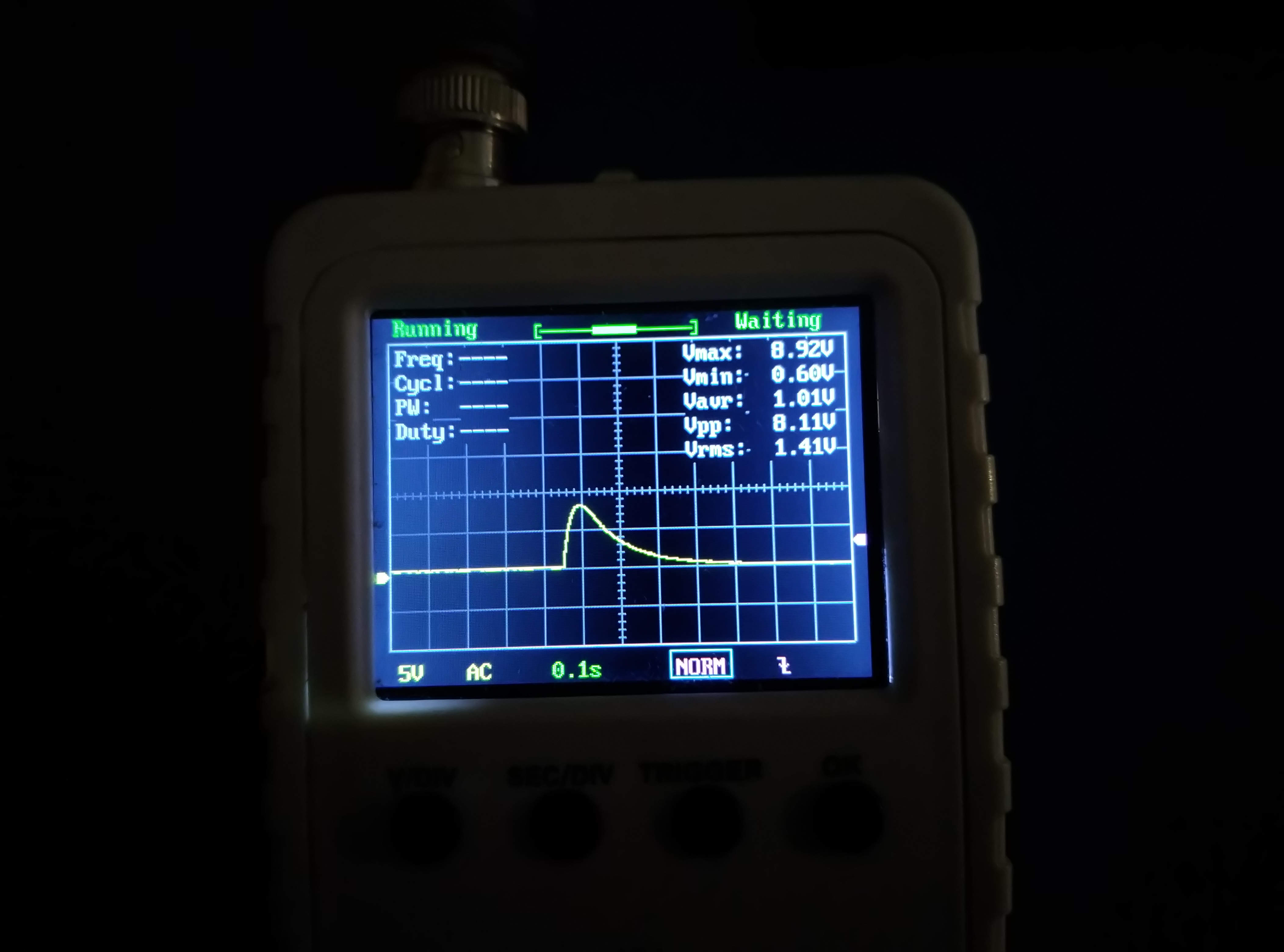
Interestingly enough, spike differed from the one I measured two days ago

PSU Turned On

On

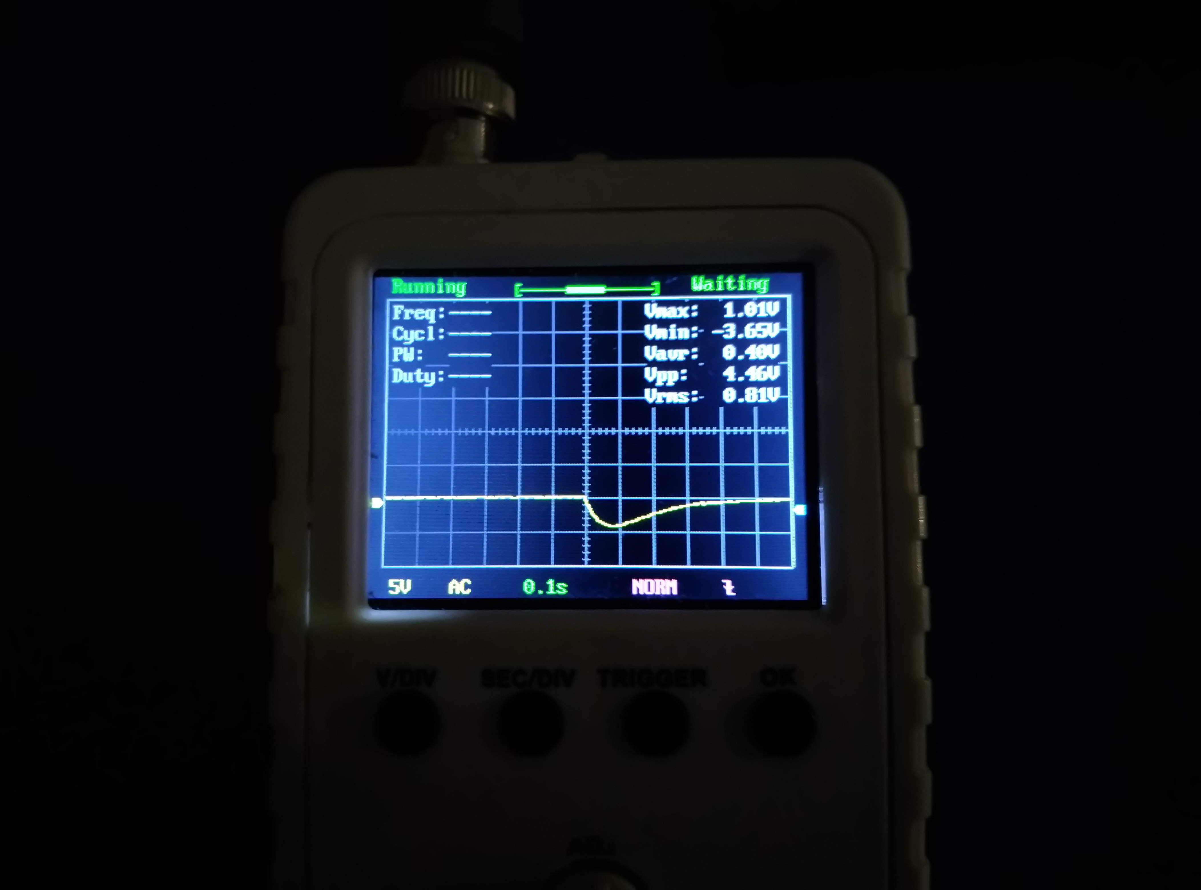
PSU Turned Off

Off

\$\endgroup\$
2
  • 2
    \$\begingroup\$ If those are the only capacitors, there might be high frequency bypass missing. Show the schematics to see any flaws in the design. Show the PCB how the components are wired, maybe wiring is too long so it adds wiring inductance. Show the measurement setup too, if the waveforms can be explained with incorrect measurement techniques. What is the input voltage to 7812? How much is the load applied to the 7812 output, and what type of load it is, inductive, capacitive, or resistive? \$\endgroup\$
    – Justme
    Commented Sep 15, 2021 at 4:22
  • 2
    \$\begingroup\$ OK, it's not a spike, you set the scope to AC so it's showing the derivative of the signal as voltage rises from 0 to the set output voltage when you turn it on... just set the scope to DC... \$\endgroup\$
    – bobflux
    Commented Sep 16, 2021 at 8:13

1 Answer 1

2
\$\begingroup\$

If a load with a lot of capacitance is connected, this will draw a large inrush current to charge the caps, so it is expected that the output voltage would drop, 7812 will go into current limit while charging the caps, and then output voltage settles to the normal value.

However, 7812 can't output a negative voltage. Worst case, it will drop close to zero but it will stay positive. If you have a negative voltage spike, not just a drop in voltage, but if it really goes below zero, then the problem is most likely the inductance of the wires (or a ferrite bead on the load) forming a LC resonant circuit with the output caps of the regulator and the input caps of the load. This will also create overvoltage spikes, and it can destroy circuits. The problematic LC circuit can also be at the input of the regulator, not necessarily at the output.

The fix is to add more damping to the LC circuit to make it critically damped instead of underdamped. For example you can add capacitance with somewhat high ESR.

It's important to diagnose this correctly because if the problem is not resonance from LC, but instead a simple drop in output voltage when the load is connected, then the fix could be to add more low ESR capacitance.

\$\endgroup\$
2
  • \$\begingroup\$ I don't think that it's resonance. The waveform looks like a textbook example of an RL circuit - exponential voltage decay can clearly be seen. I will take a photo tomorrow and post it - including the PCB, schematics and details on how I took the measurements. \$\endgroup\$
    – George
    Commented Sep 15, 2021 at 9:40
  • \$\begingroup\$ Yes, posting the waveform will help \$\endgroup\$
    – bobflux
    Commented Sep 15, 2021 at 9:52

Your Answer

By clicking “Post Your Answer”, you agree to our terms of service and acknowledge you have read our privacy policy.

Not the answer you're looking for? Browse other questions tagged or ask your own question.