3
\$\begingroup\$

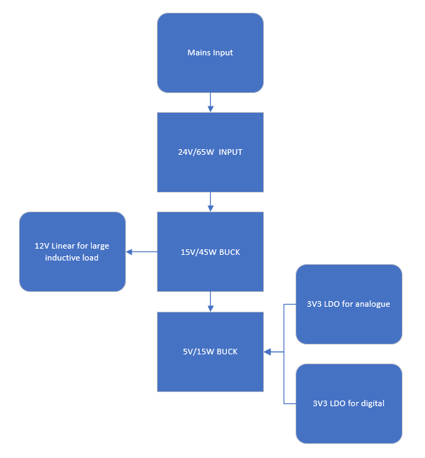
I'm designing a product that has a 24V input, but the voltage rails on the product are 15V, 12V, 5V and 3.3V. The 24V is from this supply. To get the lower voltage I've been cascading cheap modules from amazon based on the MP1584. One steps down the voltage from 24V to 15V and another feeds off the 15V to reduce to 5V. I use a linear regulator for the 12V and 3V3 rail.

enter image description here

Now my question: I need to come up with a power supply solution for this product and remove the cheap modules from Amazon. For the fairly high output power (45W and 10-15W) I require is it better to design the circuit myself or to purchase a pre-made DC-DC solution? It is important to note that I have no power supply design experience and my time on this project is limited. I see that I have two options:

  1. Design bespoke DC-DC converter circuit using an off the shelf chip for a 15V 45W output and again for a 5V 10W output.
  2. Buy a complete off the shelf module; one for 15V and one for 5V

This product isn't too cost sensitive so could spend approx. £10-15 - $20-ish on this solution.

Any suggestions are welcome.

\$\endgroup\$
7
  • 1
    \$\begingroup\$ Thanks for the suggestion Andy, but the 24V input supply is intentional. This product will be powered by mains as said in the question, but it will also have to be powered by mobile industrial machines that use 24V batteries. So rather than have different power options, I decided it would be easier to just make everything use 24V. \$\endgroup\$
    – ChrisD91
    Commented Sep 20, 2021 at 10:22
  • 1
    \$\begingroup\$ You should detail those battery supplies in your question and provide maximum input voltages (likely to be significantly more than 24 volt) and, detail what surge and spikes they are capable of and the level of ripple voltage that may be on the output. \$\endgroup\$
    – Andy aka
    Commented Sep 20, 2021 at 10:34
  • 1
    \$\begingroup\$ Unfortunately, the customer is difficult and won't/can't give me the information required regarding the battery supplies. My company is also not interested in helping me get the details, I'm the only design engineer. All I know is that the batteries are rated for 24V and are similar to car batteries. I'm focusing on designing the product for the 24V mains supply. \$\endgroup\$
    – ChrisD91
    Commented Sep 20, 2021 at 10:41
  • 2
    \$\begingroup\$ So you've got a non-cooperative customer, and a company who doesn't seem to want to help you get the needed information. Sounds like a recipe for disaster. You're in a can't win situation, because no matter what architecture you come up with, the customer or your own company may nit-pick and criticize your approach. \$\endgroup\$
    – SteveSh
    Commented Sep 20, 2021 at 11:50
  • 2
    \$\begingroup\$ In that case make sure the step down FROM 24V can tolerate at least 30V (possibly more like 32 or 36V) if those 24V battery systems may have alternators connected. A "24V" lead acid is more like 28V, or LiFePO4 chargers should stop at 29.2 (I've turned mine down to 28V to ease strain on the batteries). A reputable off-the-shelf mains to 24V stage will make safety/compliance/approvals process much easier. \$\endgroup\$
    – user16324
    Commented Sep 20, 2021 at 12:45

2 Answers 2

2
\$\begingroup\$

A custom power supply could very well do exactly what you've done, but it all comes down to your requirements. I will try to cover a few notes on your approach and how a custom power supply could do it differently.

You don't give requirements for each rail, but from what you've shown you'll have a max current draw of 3A on the 3.3V rails (combined). We'll call that 1.5A each. If you were to draw 1.5A from each 3.3V rail, you'd have no leftover power for the 5V rail. Without a way to actively limit that on the 3.3V end, you could run into a situation where the 5V rail cannot provide any power!

Similarly, if you're drawing the full 15W from the 5V buck you only have 30W left to share between the 12V and 15V rail. The 12V is limited to 3A max (15V@45W is 3A through the linear). At 30W, this drops to 2A.

Once again, this may not be a problem depending on your (or your customer's) requirements.

As some of the comments brought up, bucks are non-isolated so all of your returns are tied together. Your 24V converter is isolated, but is a medical converter (medical products are a different beast!). Having all of your returns tied together can cause ground loop issues, especially since you are essentially connecting an inductive load to the 3.3V rail which I assume powers an MCU of some kind.

Now onto a "bespoke" solution. A custom SMPS based solution would provide you with isolation between all of the rails. You could create a 24-15, 24-12, 24-5 and 24-3.3 converter and not need to deal with the efficiency hits/isolation issues that come with linear regulators.

A custom solution would allow you to control maximum output currents and control how the system behaves during an over current (or short circuit) condition.

I design power supplies for work, so give me a shout if you want to go down the custom route and I can point you in the right direction. Time is money though, and it is going to take you a while to get a system running if you have no experience with SMPS. I can also point you in the right direction for COTS products that will meet your requirements.

\$\endgroup\$
1
\$\begingroup\$

If cost is not a priority and you are not manufacturing in quantity always buy off the shelf. It saves time, money (you don't pay for the design) and legal liability if it fails

\$\endgroup\$

Your Answer

By clicking “Post Your Answer”, you agree to our terms of service and acknowledge you have read our privacy policy.

Not the answer you're looking for? Browse other questions tagged or ask your own question.