1
\$\begingroup\$

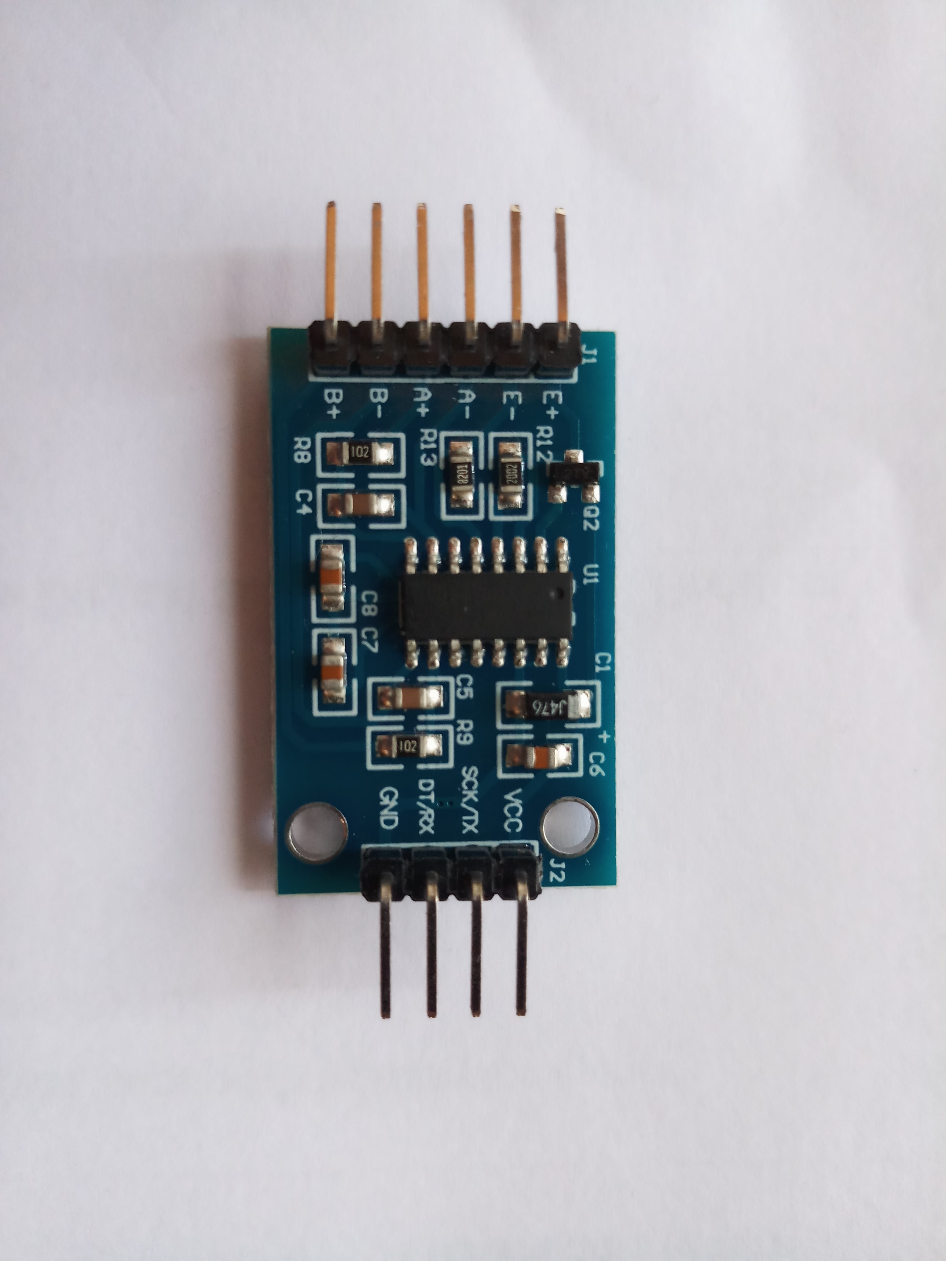
I bought the following version of HX711 module.

BOB Front

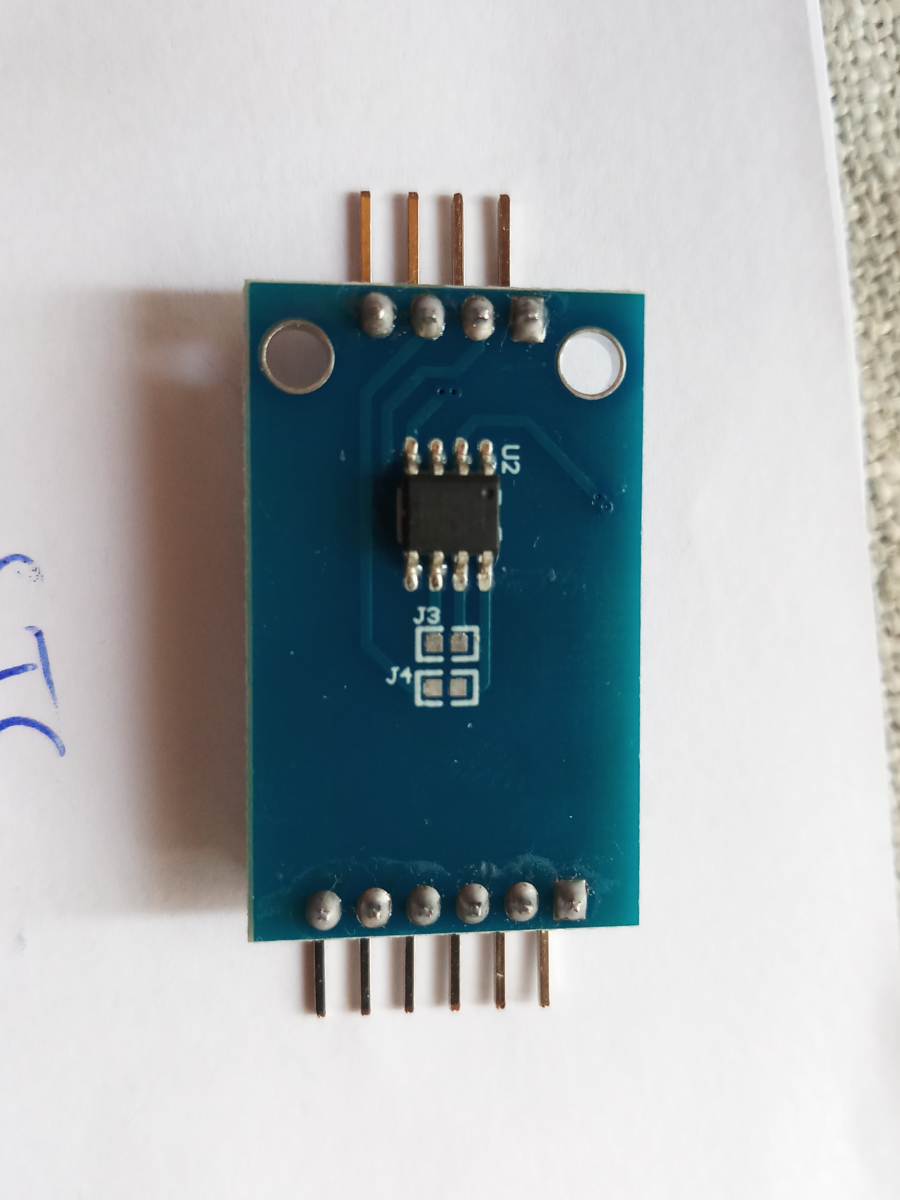
BOB Back

Connection to Arduino VCC -> 5V GND -> GND SCK/TX -> GPIO 6 DT/RX -> GPIO 7

However, it doesn't work. I have tried different libraries and even different boards but there seems to be communication problem with the module. I assume it has something to do with the mcu chip and the jumper connections J3 & j4. The mcu chip is STC 8F1k08.

There are a lot of tutorials regarding HX711 modules but I couldn't find any info about this particular board with an MCU. There is some info (chinese translation) on the sellers page but doesn't say anything about the jumper config. Product page

I tried to find any relevant info in the MCU datasheet but with my limited knowledge of MCUs it didn't help much. Apparently it's possible to communicate through Serial & I2C with this MCU.

From the datasheet MCU pinout it looks like, J3 connects SCL & Tx, while J4 connects SDA with common ground. I am confused as it seems like mixing I2C with UART.

So can someone please help me solve the communication issue?

\$\endgroup\$
5
  • 1
    \$\begingroup\$ The web site documentation says the MCU makes it serial only (default 9600 baud), so any I2C library you use will fail. \$\endgroup\$ Commented Sep 24, 2021 at 14:29
  • 1
    \$\begingroup\$ I have used this "old" HX711 to uV levels range (with digital average ) ... I don't know this "version", but it seems that you can (if any problem) however remove MCU easily ... \$\endgroup\$
    – Antonio51
    Commented Sep 24, 2021 at 14:59
  • \$\begingroup\$ @JackCreasey Most of the libraries I tried, used Serial comm. e.g. this one github.com/bogde/HX711 but it still doesn't work. \$\endgroup\$
    – Zaffresky
    Commented Sep 24, 2021 at 15:10
  • \$\begingroup\$ The library you point to is a Synchronous serial driver for the HX711 chip. The board you have wants to send Asynchronous Serial @9600 baud. \$\endgroup\$ Commented Sep 24, 2021 at 15:53
  • \$\begingroup\$ I searched for HX711 asynchronous driver but didn't find a library. So if I understand correctly the HX711 communicates via synchronous serial but the MCU chip communicates using the asynchronous serial. Guess I need to write my library to be able to communicate with this module :( \$\endgroup\$
    – Zaffresky
    Commented Sep 24, 2021 at 17:46

2 Answers 2

1
\$\begingroup\$

The other answer said just:

same problem,solder jumpers j3 and j4,remove soip8 mcu and work ok....

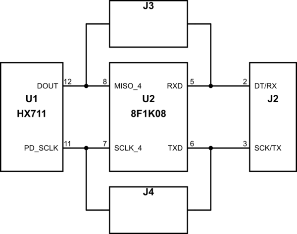
Based upon the information in the question and looking at the traces visible on the HX711 module a partial schematic is:

schematic

simulate this circuit – Schematic created using CircuitLab

Where:

  • The HX711 is a 24-Bit Analog-to-Digital Converter (ADC) for Weigh Scales which has a SPI like interface using the PD_SCLK and DOUT pins.
  • The STC 8F1K08 is an 8-pin MCU with a 8051 core, with presumably contains a UART to SPI based conversion between the TX and RX pins on the J2 connector of the module and the HX711 load cell ADC.

So, the referenced answer shows that by removing the pre-programmed MCU U2 and fitting jumpers for J3 and J4, that changes the J2 connector pins to SCK and DT to give a SPI interface to the HX711 load cell ADC.

\$\endgroup\$
0
\$\begingroup\$

same problem,solder jumpers j3 and j4,remove soip8 mcu and work ok....

\$\endgroup\$
1
  • 2
    \$\begingroup\$ user365057 - Hi, Thanks for trying to help. Can you add more details? What exactly happens when you solder across J3 & J4? Are you saying that you had to desolder the MCU or something else? etc. || If you can add more details, please edit the answer. || As you're new here, please see the tour & help center to see how Stack Exchange differs from typical forums. \$\endgroup\$
    – SamGibson
    Commented Feb 23 at 12:59

Your Answer

By clicking “Post Your Answer”, you agree to our terms of service and acknowledge you have read our privacy policy.

Not the answer you're looking for? Browse other questions tagged or ask your own question.