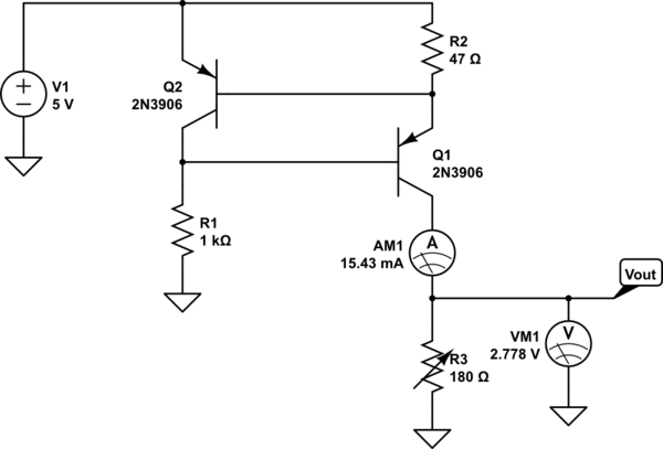
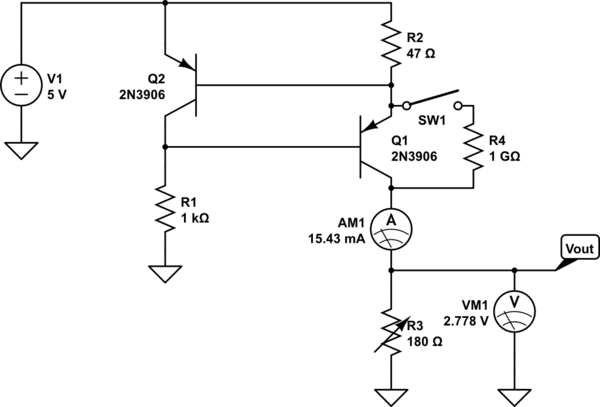
The following circuit, taken from this answer seems to give odd results when doing a parameter sweep simulation on CircuitLab. Is the problem with CircuitLab, or is there some problem with the circuit that I do not see.

simulate this circuit – Schematic created using CircuitLab
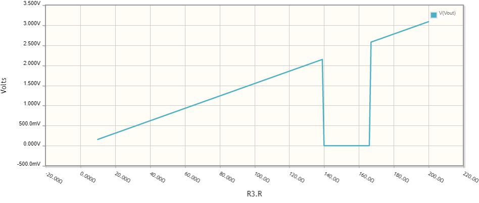
The intent of the circuit is to provide a constant current through R3 so that its value may be determined by measuring the voltage across it. When I ran a sweep which varied the value of R3 from 10 to 200 \$\Omega\$, a "notch" in the output voltage appears.
 However, the \$V_{be}\$s and \$I_b\$s of the transistors look fine.
Changing the transistors to BC327's gives an even more erratic sweep.
Removing either the ammeter or the voltmeter from the circuit makes the problem go away!
Also of interest, if the value of R3 is manually set between 140 and 166 \$\Omega\$, DC simulation gives the correct answer. The problem only seems to occur with DC sweep.
Does anyone know the cause of this, or the precise conditions under which it occurs?
Update: Checked on 19 April 2022, and problem persists.


Ω,μ,°,×,±, etc. as well as<sup>...</sup>and<sub>...</sub>in the posts (but they don't work in the comments). You don't need to use MathJAX just for a symbol. \$\endgroup\$