1
\$\begingroup\$

I am designing a TRIAC LED dimmer circuit.

Depending on the AC voltage applied, I control the gate trigger angle for the TRIAC to reduce/limit the current at 15 amperes to the load. Gate trigger control is done using a micrcontroller & MOC3021 driver circuit. There is a zero-cross detector circuit using EL-817 optocoupler which is fed into the GPIO of thr controller.

In my application, the AC voltage is either 120V/208V/240V. I want a simple circuit to detect which of these voltages are currently connected to my board and thus use corresponding trigger angle.

I found many online reference which spoke about step-down transformer, bridge+voltage divider circuit and linear opto-coupler. All these are either unnecessarily costly or space consuming for my requirement.

Does anyone know of a simple but reliable method like using a non-linear opto itself and figuring out which AC voltage line is connected to the board?

\$\endgroup\$
4
  • 1
    \$\begingroup\$ Is the microcontroller galvanically isolated from the mains? If not, you might not need an optocoupler at all! \$\endgroup\$ Commented Oct 1, 2021 at 10:11
  • \$\begingroup\$ @user253751 : Yes micrcontroller is galvanically isolated from mains. \$\endgroup\$ Commented Oct 1, 2021 at 10:25
  • \$\begingroup\$ May be 3 separate optocouplers, with different current limiting resistors. \$\endgroup\$
    – user263983
    Commented Oct 1, 2021 at 10:28
  • 1
    \$\begingroup\$ Why not just have a small control circuit that monitors the current and drives the Triac accordingly to obtain 15 amps? Why use a MCU and over-complicate things? \$\endgroup\$
    – Andy aka
    Commented Oct 1, 2021 at 11:49

2 Answers 2

6
\$\begingroup\$

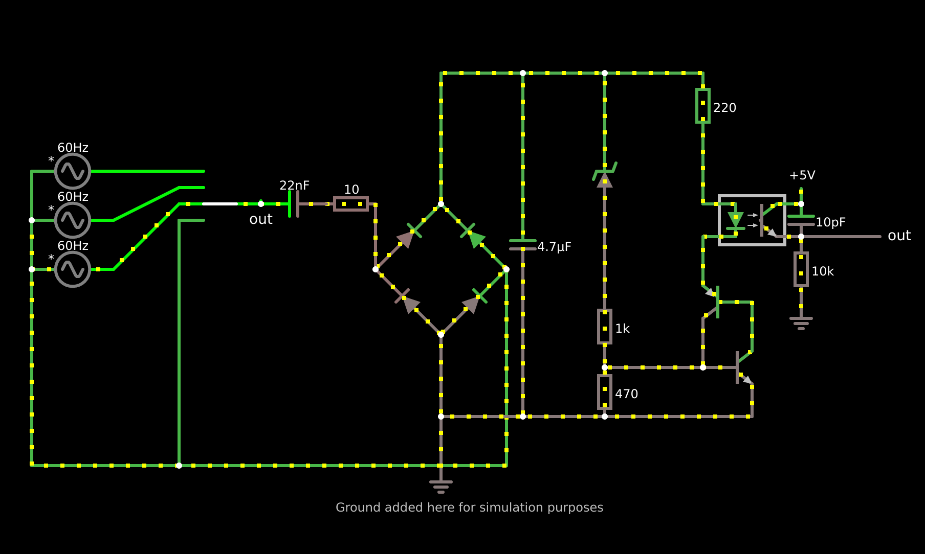
Use a capacitive dropper to convert the input voltage and frequency into a constant current source, and use that trigger an output optocoupler. Then count the pulses per second to compute the input voltage
enter image description here

link to simulation

This gives an output of about 15Hz on 120Vrms@60Hz, 24Hz on 208Vrms@60Hz and 30Hz on 240Vrms@60Hz

Note that the output can also been seen as 8 half cycles between interrupts at 120Vrms, 5 half cycles between interrupts at 208Vrms, and 4 half cycles between interrupts at 230Vrms. The circuit relies on the fact that the capacitive dropper stops supplying current in the peaks to break the latch

Math

Every cycle, the input voltage goes from 0, to Vpeak, to 0, to -Vpeak

In these cycles, the input 22nF capacitor gets charged and discharged.

This generates pules of current though the birdge rectifier and charges the 4.7uF capacitor

Lets assume our input voltage is 240Vrms at 60Hz, this makes the reactance of the 22nF capacitor about 120.572 kOhm, we have to add our inrush resistor to this to get 120.582 kOhm of "input resistance", We have to subtract 1V from our input voltage for the bridge rectifier, to get (240V - 1V) / (120572ohm + 10ohm) = 0.001899A = 1.899mA

Using the capacitor charge formula of "dV = I dT / C", we can calculate the time it takes to reach our trigger point, which can even be low 11V as most zener diodes have a smooth curve (we an make a more perfect circuit using a more precise voltage reference).

11V = 0.001899A * dT / 0.0000047 ==> dT = 0.0272249sec (36.7310807386Hz)

This value seems to low/high for the previous measurement of 0.03333 sec (30Hz). This is caused by the fact that this is only the time for the capacitor to charge to the trigger level, and once the PNP+NPN transistor is latched, it keeps being lathed until the base voltage on the NPN drops below 0.5, which happens below 1mA input current (every vPeak crossing). This means the circuit is limited to 1 pulse every 0.0083333333 sec (120Hz)

The 240Vrms takes 4 of these "mains half cycles", which is 0.333sec, as 3 half cycles only take up 0.025sec, which is barely below the trigger treshold

One advantage of measuring the time in half cycles, is that the whole voltage measuring process becomes frequency independent, as it still takes the same amount of time in half cycles. (and you already have a zero crossing sensor)

The total formulae becomes:

X = 240, Z = 60, Y = 0.000000022, R = 10, 0.0000517 / ((X - 1) / (1 / (2PI * Z * Y) + R))= 0.026084 seconds per capacitor charge

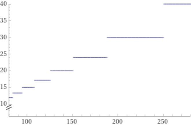
X = 240, Z = 60, Y = 0.000000022, R = 10, ceil(0.0000517 / ((X - 1) / (1 / (2PI * Z * Y) + R)), 1 / Z / 2) = 30Hz

Or in a plot form (with fixed 60 operating frequency, and fixed 10 ohm inrush resistor)
The plot from the above formulae

\$\endgroup\$
4
  • \$\begingroup\$ Thanks a lot. This is really useful circuit. I made this circuit and measured using arduino. Works perfectly fine and we can detect voltage accurately using software filters. Can you please share any link that explain how to do design calculation? For others who are trying this, Here is my video : imgur.com/a/TW3rs00 I used arduino to read the frequency of pulses. Arduino code : github.com/vishweshgm/StackExchange_ACVoltageDetector \$\endgroup\$ Commented Oct 7, 2021 at 14:19
  • \$\begingroup\$ I tried to do math for calculating how much time would it take for capacitor(4.7) to reach 12V (referring to simuation) after which it discharges via current sink. But I am unable to arrive at an equation which define time taken by Capacitor (4.7uF) to reach 12V. Can you please help me understand how this circuit decides the frequency of pulses? \$\endgroup\$ Commented Oct 8, 2021 at 13:17
  • \$\begingroup\$ @VishweshGM I added a math section explaining it \$\endgroup\$
    – Ferrybig
    Commented Oct 8, 2021 at 14:42
  • \$\begingroup\$ You are amazing! Thanks again. \$\endgroup\$ Commented Oct 14, 2021 at 11:10
1
\$\begingroup\$

In the past, I used a delta-sigma ADC on the high voltage side, and sent the "digital" signal over the opto. Software on the microcontroller can then decode the measured value.

The ADC and isolation can be integrated into a single chip.

\$\endgroup\$
1
  • \$\begingroup\$ You can even just use a delta-sigma modulator (effectively a 1-bit ADC) so you don't need to worry about complicated serial protocols or isolating multiple bits of information. \$\endgroup\$
    – Hearth
    Commented Jul 1, 2023 at 16:57

Your Answer

By clicking “Post Your Answer”, you agree to our terms of service and acknowledge you have read our privacy policy.

Not the answer you're looking for? Browse other questions tagged or ask your own question.