If you plan to use a zener, then the key idea to hold in your head is that the zener will start conducting when sufficiently reverse-biased. You also need to keep in your mind that you'll need a series, current-limiting resistor to protect the zener as well as to operate it at the correct (datasheet) current (which varies depending on the zener's nameplated voltage.)
So, you have two parts in mind now. Just use your imagination about how to keep a transistor off when there's no current and then on when there is current. That's the only problem to solve in your mind.
A BJT transistor is on when it's \$V_{\text{BE}}\$ is forward-biased, sufficiently. It's off, otherwise. (That's a gross simplification, but so long as you imagine "less than \$400\:\text{mV}\$ means off and more than \$550\:\text{mV}\$ it is starting to be on" then you won't be too far afield.)
Hmm. If the zener conducts then there must be a voltage drop across that current-limiting resistor. And if not, then there will be no voltage drop across it. Sounds like a fit -- maybe, anyway.
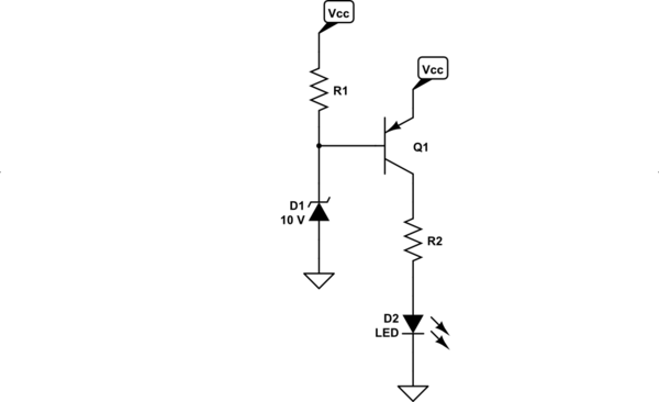
So what about:

simulate this circuit – Schematic created using CircuitLab
It almost looks okay. Using the overly-simplistic argument I just made, this circuit looks like it may work well. When the zener is 'on' then there will be a voltage drop across \$R_1\$ and that should turn on the BJT. And it does. So, technically, it will turn on the LED at "some determined voltage," now.
The problem with it (well, the bigger problem anyway) is that once on and as the supply voltage rises still further then the BJT base will start supplying insane levels of current into the zener. That will probably not comport with your:
I need it ... low consumption
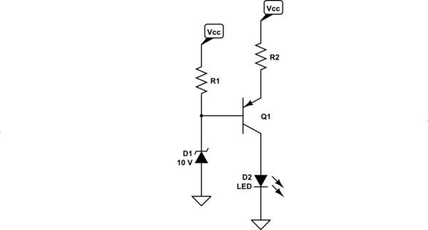
So, another cheap idea is to just move the LED resistor to the other side of the BJT. That should limit the ability of the BJT base to jam current into the zener, because the emitter resistor will be in the way of it.

simulate this circuit
Now, if you try this arrangement, it will much better meet your requirement as well as turning the LED on at a particular threshold.
The problem with this arrangement is that now it is a voltage-dependent current source to the LED. Let's say \$R_1=R_2=1\:\text{k}\Omega\$. Then the max LED current will be about \$2\:\text{mA}\$. But that LED current will decline linearly with lower voltages. So the brightness will be less when the voltage is less. This may be acceptable. I cannot say.
But the point of the above is to use your imagination and just think, a little. Turn things over in your head in different ways.
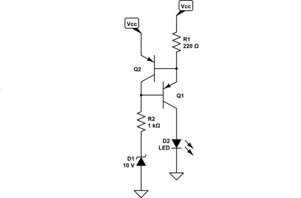
Here's another simple approach that minimizes the voltage-dependent current source period and makes it more of an on/off circuit -- through it still has its "behaviors."

simulate this circuit
That might perform acceptably. Now, \$R_1\$ sets the LED current and because this is a voltage-independent current source (once sufficient voltage overhead is reached), it behaves more like on/off than the earlier circuit.
These aren't by any means the only ideas that come to mind. There are countless ways to do this. For example, the very first thing I may want to do for a low power unit is to avoid the zener. You already may only want about \$1\:\text{mA}\$ or maybe \$2\:\text{mA}\$ in the LED. That's bad enough. You don't want to have to waste about the same amount (or still more) when feeding a zener diode. So you may want to look for a lower-current "zener-like" circuit for the voltage comparison part of this circuit.
You cannot do anything much about the LED, except to buy as high-efficiency LED as possible. But once that's decided, you are stuck with its requirement. The only thing left is to worry about the voltage comparison part. And much can be done on that front.
For example, Diodes Inc has the AP431S, which is very low current (tens of microamps) and can be set to a desired voltage, as well.
In addition, BJTs require recombination currents. These can be quite modest -- absolutely no more than 10% but can be 1% or so. And that isn't usually a big deal. But a FET can use even less. So if you get to the point of really wanting to squeeze the last few current-pennies out of the circuit, then you might consider using more expensive FETs and modifying the design once again.


