4
\$\begingroup\$

I am preparing to do some RF mixer experiments with the SA612 Gilbert cell mixer. I started out with the impedance matching as I understand that the input and output need to be matched. From what I read, the impedance should match 1500 ohm single or 3000 ohm in a balanced configuration. So I need to match 50 to 3000 when using a balanced configuration.

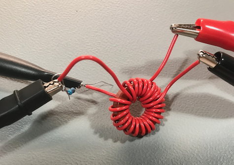
I decided to try winding a toroid. I used a T 80-2 (red, which should be good below 30MHz) with 23:3 turns:

enter image description here

But before I move on, I would like to measure it. I don't have any experience with this, so I would like to get a feeling if and how well it performs.

But how? I have some basic equipment (scope, signal gen, nanoVNA, etc,) but I don't know how to approach this.

At first I was thinking of doing some tests with the nanoVNA (I'm no expert in using it). I figured an SWR value would give me a good indication. But I wasn't able to get a good reading (I got extremely high or even negative SWR values). Maybe because the setup I used (I terminated the high-Z side with 3000 ohms as if it was connected to the SA612). I also wondered how this would work, I mean, doesn't the nanoVNA just see an inductor (the primary side of the transformer) and doesn't this not just act like one (with somewhere a dip where it's resonant)?

Then I figured I could do some measurements with my signal generator and an oscilloscope. I connected the signal generator to the low-Z side and tried to measure the high-Z side which was again terminated by a 3000 ohm resistor (gnd and probe on each side of the resistor). I could not get any reading (even at the lowest setting in the mV range and with 10 Vpp). I inserted a 50 ohm resistor in series with the signal gen to see if the signal is visible at the input side and it was as expected.

So, now I have built myself this mysterious device that should work, but which I can't measure...

My question: Can anyone explain how to measure an impedance transformer? And please elaborate and be explicit, as I am quite new to this particular area.

**Edit-1

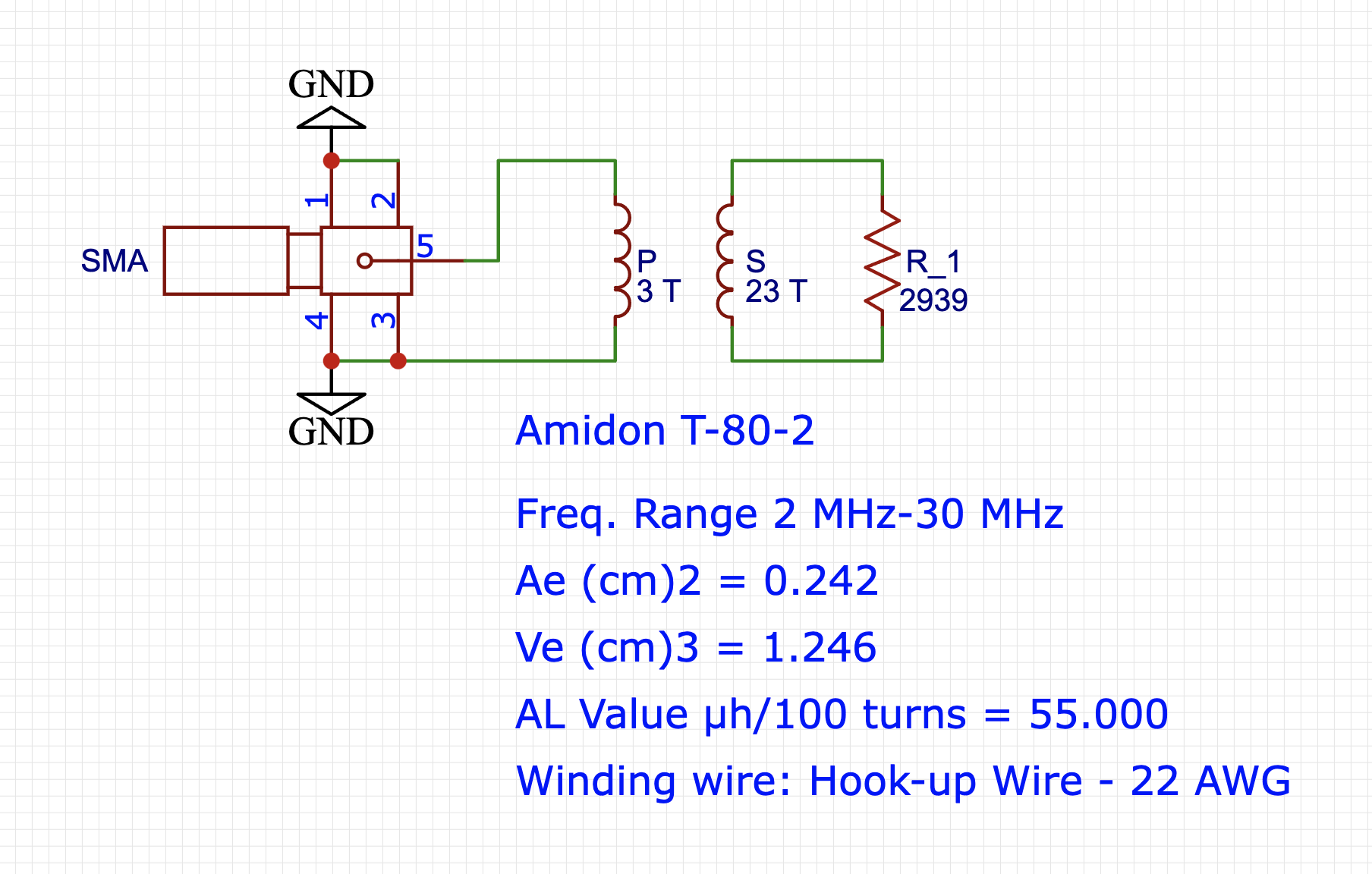
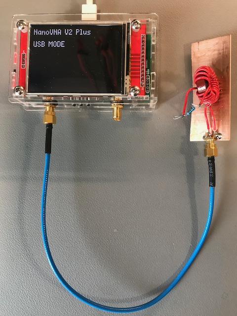
Test setup for measuring impedance:

enter image description here

enter image description here

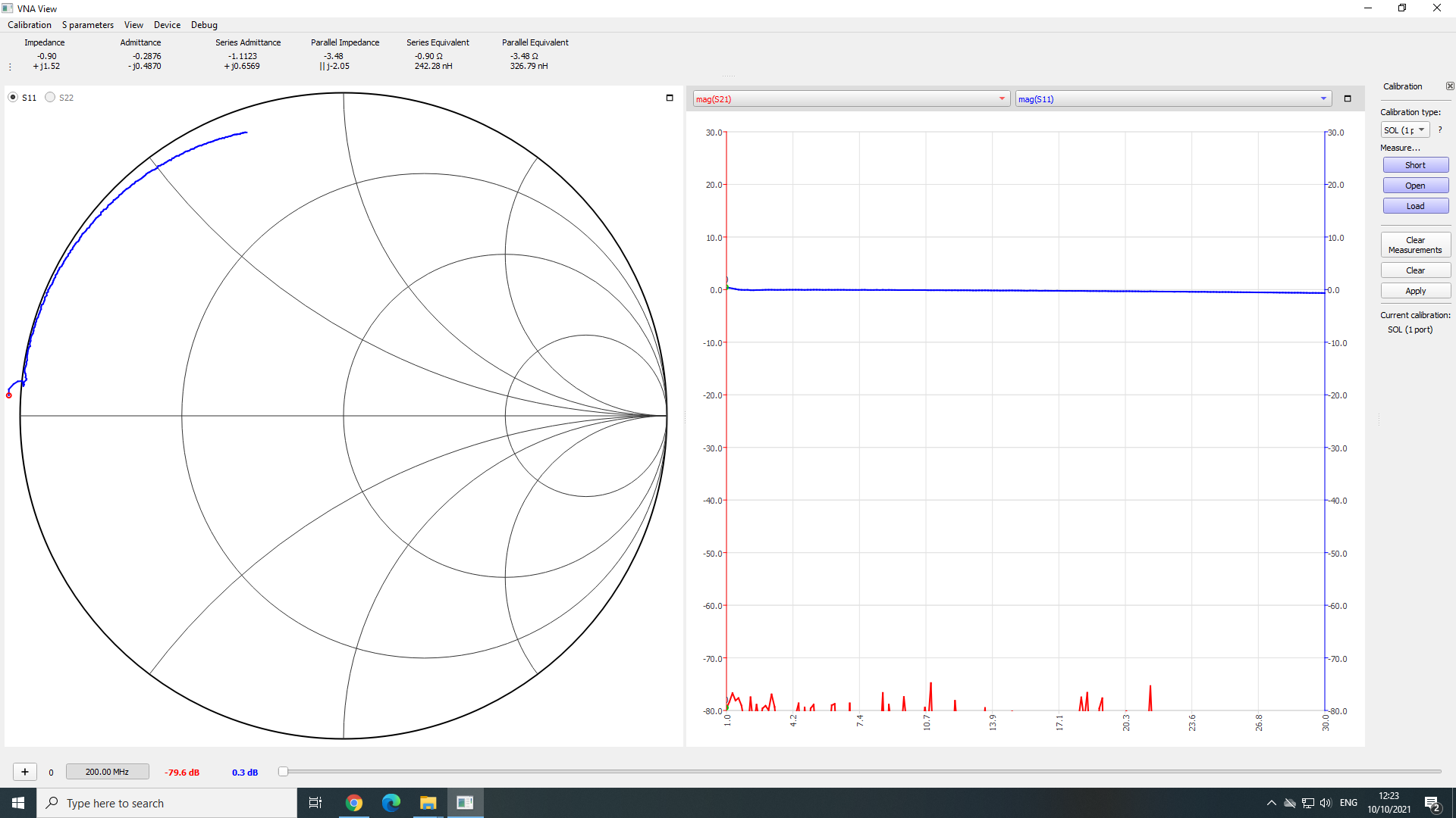
Result after calibration (calibrated at the end of the cable used):

enter image description here

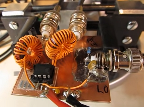
I was inspired by this video from Ham Radio operator W2AEW. His toroids "look" the same, and he didn't use enameled wire. So I was hoping I would come close to his results this way.

enter image description here

**Edit-2

The datasheet I used for the toroid values as stated for the current test: datasheet

The sweep on the nanoVNA was set to 1 MHz - 30 MHz. I'm not sure what signal level the nanoVNA is using (I would have to investigate that) but what I am planning for my SA612 experiment will be:

LO -50dBm @ 17.7 MHz, RFin -50dBm @ 28.4 MHz

expecting a response at 10.7 MHz

I will move on by finding a (ferrite) toroid with better properties for this. As I have no experience with this, I probably have to order and test multiple candidates and see if they match (calculated) expectations.

I found this document to be useful: Inductor Construction

I calculated that for Z=50 (which would be 0.00053 mH inductive) a ferrite core with 3 turns would need an Al of ~60 mH/1000. This would lead to a toroid FT-114-61 (which is 79.3) as closest. So that I am going to try.

The mentioned document immediately makes clear that for wideband use the iron core toroids are not useful. So things fall into place...

\$\endgroup\$
6
  • 1
    \$\begingroup\$ 1. What's the input/output impedance on nanoVNA? 2. Use schematics editor to draw how did you connect and how did you put the resistors (and their values). \$\endgroup\$ Commented Oct 9, 2021 at 20:49
  • 1
    \$\begingroup\$ 26 turns yields only about 3 uH inductance - not enough for a wideband transformer. You'd like the inductance value to be maybe 5-times the SA612 output resistance (in your case...3000 ohms) at the lowest frequency of interest. Adding a parallel capacitance raises impedance, but narrows the bandwidth a lot, because now it is a resonator. Winding a wideband transformer for such high impedance is rather difficult - did you really intend to do this? \$\endgroup\$
    – glen_geek
    Commented Oct 9, 2021 at 20:57
  • \$\begingroup\$ @MarkoBuršič I added some additional info. \$\endgroup\$ Commented Oct 10, 2021 at 11:08
  • 1
    \$\begingroup\$ @glen_geek I was inspired by this [youtu.be/Mm7WfVzr1ao?t=463](video) from w2aew. His toroids "look" the same, I mean, he didn't use enameled wire. So I thought I would come close to his results like this. \$\endgroup\$ Commented Oct 10, 2021 at 11:14
  • \$\begingroup\$ "I decided to try winding a toroid. I used a T 80-2 (red, which should be good below 30MHz)" -- The color does not always indicate the toroid material, just possibly from a particular manufacturer. \$\endgroup\$ Commented Oct 10, 2021 at 14:13

2 Answers 2

2
\$\begingroup\$

I decided to try winding a toroid. I used a T 80-2 (red, which should be good below 30MHz) with 23:3 turns

There is no evidence that the toroid you picked is actually any good below 30 MHz at all. You need to examine the data sheet and the performance graphs for the material to make this judgement. In my experience, you cannot assume it will be any good.

Anyway, moving on, let's assume it is good for frequencies up to 30 MHz. To make this assumption and knowing that it is a toroid (no gaps) it must be made from specialist low permeability material. It might have an inductance factor in the region of 100 nH per single turn for it to be good up to 30 MHz.

With three turns, that's a total primary inductance of 900 nH. If your operating frequency is (say) 10 MHz, 900 nH has an impedance (irrespective of what you connect to the secondary) of 56.5 ohms reactive. At 1 MHz the impedance is 5.65 ohms reactive.

So, if your testing frequency is 1 MHz (or lower), it's going to have a pretty shabby input impedance and not at all operate as an impedance transformer.

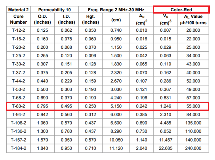
New information about the core

enter image description here

The above table extracted from this data sheet.

As I suspected; it's a very low permeability core with 100 turns producing an inductance of 55 μH. Given that inductance is proportional to the square of the turns, the inductance of 1 turn will be 100² lower at 5.5 nH. Hence, 3 turns will be about 50 nH. At 10 MHz, this has a loading impedance of 3.11 Ω reactive and will just get linearly worse at lower frequencies.

When you are designing an impedance transformer you want the loading impedance of the primary inductance to be significantly higher than the impedance projected to your primary from the secondary.

Can anyone explain how to measure an impedance transformer?

It sounds like you are measuring it correctly with the signal generator but, you are anticipating an ideal impedance transformer and neglecting the very significant effect of the primary loading (magnetization) inductance. Thus, your results confuse you because you are expecting to see about 50 Ω when, in fact you are seeing closer to zero ohms. You should also state what test frequency you used so I can give a better numerical answer.

\$\endgroup\$
6
  • \$\begingroup\$ Andy, please see Edit-1 for more info on the toroid used. Also see my comment to @glen_geek where I point to a video of w2aew. \$\endgroup\$ Commented Oct 10, 2021 at 11:17
  • 1
    \$\begingroup\$ @MajodiPloegmakers I’m sorry but I’m not watching a video. 100 turns to achieve 55 uH? Is that correct? If you have data sheet links to the toroid then that is the way to go. Also, explain what test frequency you were using for measurements. \$\endgroup\$
    – Andy aka
    Commented Oct 10, 2021 at 11:36
  • 1
    \$\begingroup\$ 100 turns for 55 uH is 50 nH for 3 turns given that inductance is proportional to turn squared. That’s far too low by a mile. \$\endgroup\$
    – Andy aka
    Commented Oct 10, 2021 at 11:44
  • \$\begingroup\$ So, how does he get the core he needs? \$\endgroup\$ Commented Oct 10, 2021 at 14:14
  • 1
    \$\begingroup\$ @MicroservicesOnDDD he needs to read my answer and confirm what I suspect to be truth. Then he needs to state what actual frequency range he needs. Then he needs to reveal the signal levels involved in the real thing he's trying to make. Then I might be able to guide him but, remember EE isn't a product recommendation site. \$\endgroup\$
    – Andy aka
    Commented Oct 10, 2021 at 14:30
4
\$\begingroup\$

Supplementing Andy's answer...
The VNA test setup seems reasonable, provided the instrument is calibrated (calibration not addressed here).

A T80-2 (red) iron-powder toroid core has a low permeability, and is primarily meant for tuned-circuits, not so much for wideband transformers. Because of its low-permeability and partly because of its toroid form, coupling between two windings is not 100% as it would nearly be if permeability was much higher.

The turns ratio of 3:23 would be reasonable for matching 50:3000 ohms if coupling was 100%. From personal measurements of similar toroids, coupling between windings was measured to be about 30%. If so, more than three turns would be needed to yield a good impedance match.

Close-wound toroids have significant capacitance between turns. The result is a self-resonant frequency where winding capacitance resonates with inductance at some high frequency. From experience, I'd guess self-resonant frequency might be somewhere in the 30 MHz ballpark, where the 23-turn winding's inductive reactance is equal to the reactance of inter-winding capacitance. The inter-winding capacitance of the 3-turn winding is much smaller, and might show up at a much higher frequency.

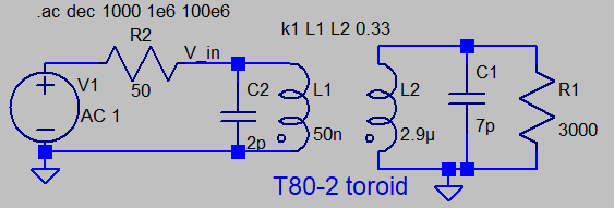
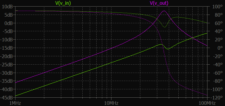
The LTspice run shown below roughly represents OP's VNA test setup. The 7pf capacitor is a single component representing the inter-winding capacitance. Self-resonant frequency shows up at about 37 MHz in the frequency-sweep plot. This transformer would be useful at that frequency (if turns ratio was adjusted for a proper impedance match). When attached to the mixer chip, this resonance would shift to a lower frequency because of the added NE612 output capacitance of a few picofarads.
LTspice schematic LTspice frequency plot
At lower frequency, the winding inductance is too low compared with the associated resistances...the 50 ohm source sees an inductive reactance that is much lower due to the 3-turn winding. For a wideband transformer, inductive reactance should be significantly higher than the 50-ohm source resistance at the lowest frequency of interest. In the LTspice sweep plot, phase seen by the VNA (at V_in) is near 90 degrees, indicating that it is seeing mostly inductance rather than resistance.


Now let's try for a wideband coupling transformer matching 3000 ohms from NE612 mixer output Z to a 50-ohm load.

I've chosen a common ferrite transformer FT37-43 that has much higher permeability than the former T80-2 core:

  • T80-2 has \${5.5 nH \over {t^2}}\$
  • FT37-43 has \${350 nH \over {t^2}}\$

You get far more inductance with few turns with the ferrite toroid. The downside is that losses are higher, so it is a poor choice for tuned circuits. The upside is that coupling between turns is very high - very near 100%.

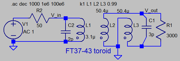
In the example below, the 3000 ohm side of the transform is connected to TWO equal windings...in this mixer circuit, the center-tap could be connected to SA612's DC supply voltage point - a point of symmetry. Each L2,L3 winding is 12 turns. The L1 winding to the 50-ohm source has three turns - the turns ratio of (12 + 12):3 is a reasonable match for 3000:50 ohms when coupling is 100%.
LTspice cannot easily model the internal ferrite losses, which are frequency-dependant. Because few turns are required on a smaller core, inter-winding capacitance is a bit smaller than the previous case.


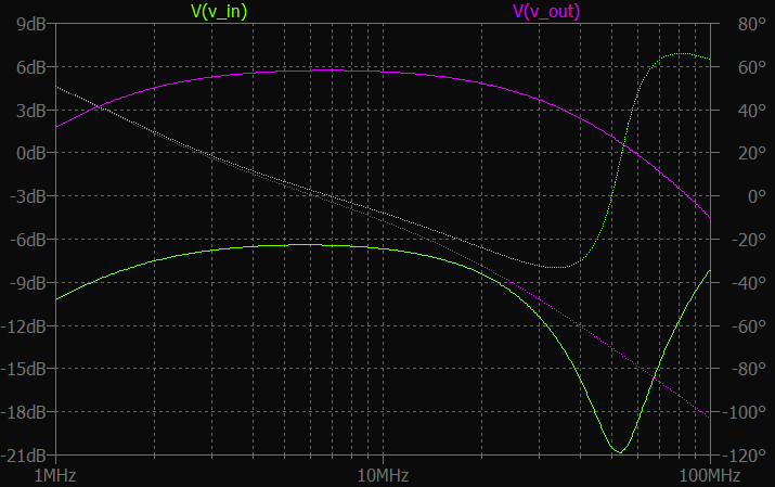
This transformer provides a reasonable match over a span of frequency from a few MHz to about 20 MHz - this might be called wide band. Note that phase angle seen from the driven 50-ohm end is low, indicating that resistance dominates the transformer's inductive reactance. Ideally, amplitude at V_in should be -6 dB, if impedance is properly matched to the 3000 ohm load.
ferrite toroid schematic LTspice wideband AC plot Bear in mind that matching such a high impedance over a wide bandwidth is difficult. Wide-band matching low impedances is much easier.

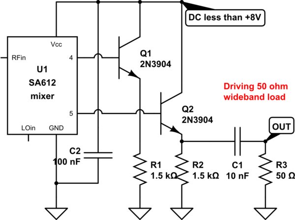
An option to consider uses emitter-followers to drive a low-impedance load. This is both wide-band, and yields power gain, since mixer output voltage is not stepped down by a transformer's turns ratio:

schematic

simulate this circuit – Schematic created using CircuitLab

\$\endgroup\$
1
  • \$\begingroup\$ Wow, thank you for the simulations. I used LTSpice (on a Mac) a few times but I need more practice with it. It could point me in the right direction before using actual parts in a setup. I will have to read this a few more times and see if I fully understand. Thnx \$\endgroup\$ Commented Oct 11, 2021 at 10:30

Your Answer

By clicking “Post Your Answer”, you agree to our terms of service and acknowledge you have read our privacy policy.

Not the answer you're looking for? Browse other questions tagged or ask your own question.