4
\$\begingroup\$

So, I am using a constant-current LED driver from the TLC592x series. This driver allows you to tune the current for all of its channels with a resistor RIREF.

tlc592x

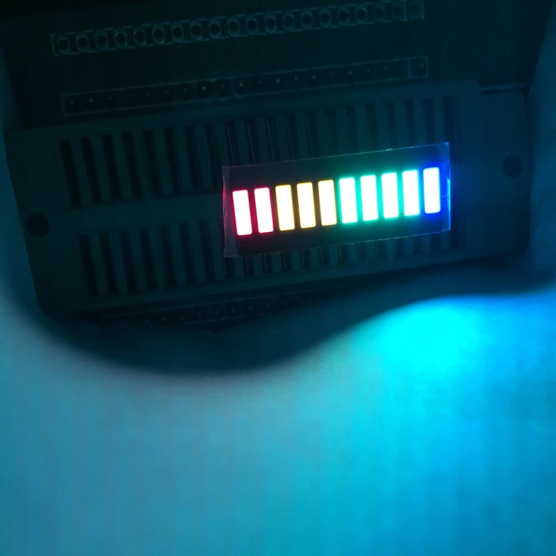
The outputs are used to drive a LED bar that has different colour segments.

enter image description here

The problem with different colours in a single bar, is that the GRN LEDs are far brighter than e.g. RED, YLW or BLU, at identical current.

I know that I can tune all the outputs of the TLC592x in unison with the RIREF resistor.

But what if I want to change the brightness per channel, while maintaining identical amperage? (I am targeting 2mA or so per channel of each driver.)

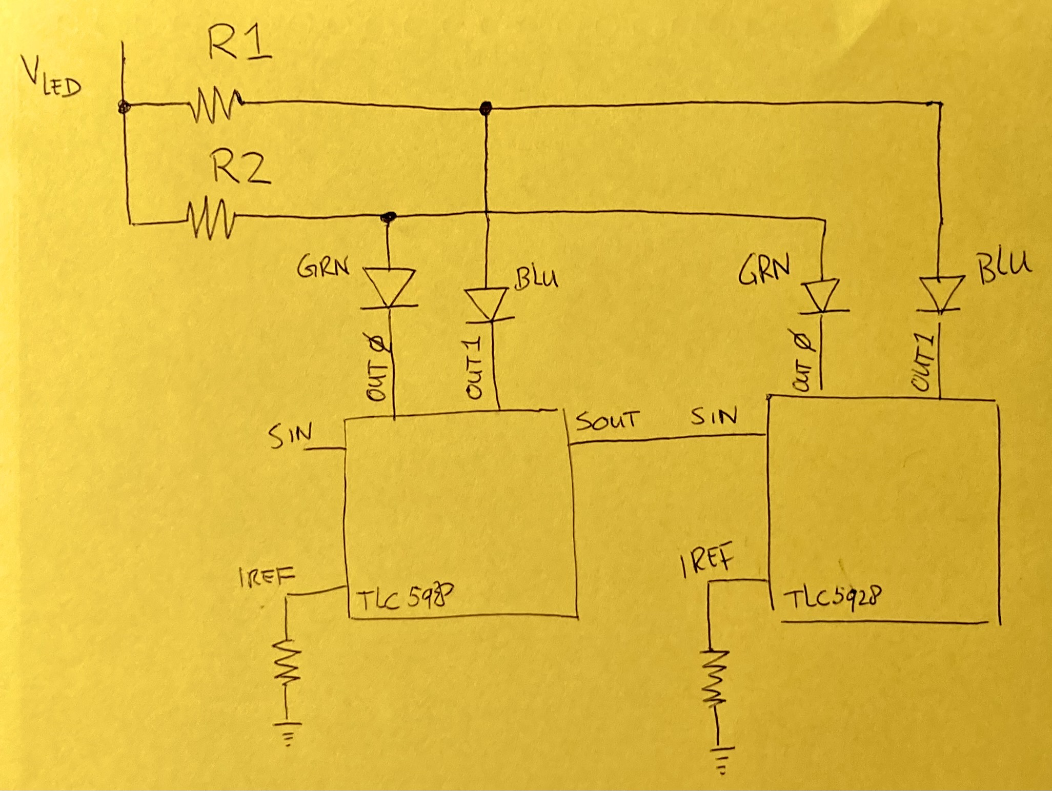
Is it as simple as adding resistors between VLED and the LED anode? With a higher resistance for the green LEDs, and a lower one for the blue ones? (Shown as R1 and R2 below?)

schematic

NOTE: In my application, VLED is 3.3V at 300mA or so. And I use 10 of the 16 channels of each driver, with 10 drivers daisy chained.

Also: if this is indeed possible, is it wasteful? Would I be producing more heat and less light, or is that effect negligible? (I thought of doing PWM on the VLED, but Arduino PWM outputs will never be able to source the current, I think.)

\$\endgroup\$
4
  • 2
    \$\begingroup\$ Why not use one driver for all the green ones, and set that one at a different current than the other drivers? \$\endgroup\$
    – Hearth
    Commented Oct 10, 2021 at 5:05
  • \$\begingroup\$ @hearth had considered it, but it poses logic problems (i treat values as asigned to a bar, as I shift them through the system) and also on the pcb, i want to pair the driver and ledbar. Not a driver and a segment group. \$\endgroup\$
    – Bram
    Commented Oct 10, 2021 at 5:57
  • 1
    \$\begingroup\$ You could switch to a different TLC59xx driver which has DOT correction (individual channel brightness control) like the TLC5922. However, I haven't seen one that is footprint compatible with the TLC5928. I thought there was that uses a longer serial protocol to transfer channel data. The TLC5922 for instance has 32 pins instead of 24. Edit: maybe the TLC5948A is what you're looking for? \$\endgroup\$
    – ontrack
    Commented Oct 10, 2021 at 9:28
  • 1
    \$\begingroup\$ I think your idea to PWM Vled is good. You'll probably need to use a high-side switch circuit which (depending on the rest of your circuit) could be as simple as a P-channel MOSFET. \$\endgroup\$
    – brhans
    Commented Oct 10, 2021 at 14:45

2 Answers 2

5
\$\begingroup\$

If it really is a constant current driver then adding a resistor in series won't help. You need to add a resistor in parallel with the LEDs, so some of the constant current will go through the resistor instead of the LEDs.

\$\endgroup\$
2
  • \$\begingroup\$ Thanks! I can't spare a R for each of the 100 LEDs. About the series resistor: would it not lower the voltage seen by the LED and with same current cause less wattage for the LED? And less light? Or do LEDs not work that way? \$\endgroup\$
    – Bram
    Commented Oct 10, 2021 at 2:06
  • 3
    \$\begingroup\$ @Bram The voltage seen by the LED is determined only by the current, which is constant. That is the whole point of a constant current driver; the LED brightness is independent of resistance, wiring, etc. \$\endgroup\$ Commented Oct 10, 2021 at 3:15
3
\$\begingroup\$

You are defeating the Rext-controlled current by limiting the voltage and current with discrete R's for each and every Green LED. Yet it can be done by trial and error.

It will be sensitive to supply voltage changes (if any), as 50% bright drop in Vf might occur with a 5% drop in Vdd as LED's are like zeners with a typical voltage range of 10% from bright to dim.

This is the advantage of the R-ext controlled current for globally dimming all LEDs.

It can also be done by shunting current with a parallel bypass R which has the effect of starting to turn on the LED at the bypass threshold so that it can match the dimmer colours at a higher setting. This would be less supply sensitive, but waste the power otherwise used by Green .

Either way, it will be trial and error to determine overall brightness desired and how much to bypass to match your eyes. Judging by 5:1 brighter level, R_green may have to absorb 80% of the current setting for each LED @ Vf

\$\endgroup\$
3
  • \$\begingroup\$ Thanks. Could I instead somehow put a duty-cycle on V<sub>GRN</sub>? For blue, supply a steady VCC, but for green, interrupt it? My arduino pins can only source 40mA though, so I would need to work around that somehow? \$\endgroup\$
    – Bram
    Commented Oct 10, 2021 at 2:14
  • \$\begingroup\$ that would work with a 20% duty cycle to Vdd give or take for 20 Grn LEDs each taking 2 mA at 1kHz give or take %. then you can Rext globally dim equally. \$\endgroup\$
    – D.A.S.
    Commented Oct 10, 2021 at 2:29
  • \$\begingroup\$ @Bram, "my [MCU] pins can only source [X] mA" is why we have transistors. I don't particularly recommend asking an MCU to supply more than about half its rated current directly. If you even think you might need more, use a transistor. \$\endgroup\$
    – Matthew
    Commented Oct 9, 2023 at 22:31

Your Answer

By clicking “Post Your Answer”, you agree to our terms of service and acknowledge you have read our privacy policy.

Not the answer you're looking for? Browse other questions tagged or ask your own question.