1
\$\begingroup\$

I need to measure current though a sensor and feed it to the ADC of a micro-controller. The ADC input voltage range does not match the sensor's output voltage range. I searched and found that op-amps solve this problem. However, I need to know the output impedance of the sensor or input impedance of op-amp (both same.) Does the burden resistance used at the output of sensor represent the output impedance of the sensor? If not then how can I calculate it?

I have attached the image for reference. I'll be using some other op-amp instead of OPA320 mentioned in this image. My purpose for asking the question is to get some help in selection of suitable op-amp and input/output resistor, capacitor etc. I am using a closed loop Hall effect current sensor to measure around 50A square wave AC current and feed it to the ADC. There is no limit to burden resistance as per datasheet of the current sensor. This is the datasheet for the sensor.

Vin at the input of the op-amp will be the output of the current sensor and practically will introduce some resistance that will affect the operation of ADC drive circuit. I need to know this output resistance of the current sensor. The sampling frequency for the ADC will be 25 kSPS and I cannot allow more than 400 ns as total ADC conversion time for one sample.

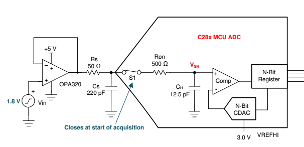
ADC drive circuit

\$\endgroup\$
4
  • 2
    \$\begingroup\$ Which sensor is it ? An opamp circuit's input resistance depends a lot on the exact circuit so a schematic would be needed. Welcome to ee.se. \$\endgroup\$
    – tobalt
    Commented Oct 12, 2021 at 8:35
  • 1
    \$\begingroup\$ Hall effect sensors don't need a burden so your question is unclear. \$\endgroup\$
    – Andy aka
    Commented Oct 12, 2021 at 11:59
  • \$\begingroup\$ @tobalt I have elaborated the question. Please have a look again. \$\endgroup\$ Commented Oct 12, 2021 at 12:32
  • \$\begingroup\$ @Andyaka datasheet mentions that they need sense resistor. I have attached the datasheet in updated question. Please look and inform if I am missing a point. \$\endgroup\$ Commented Oct 12, 2021 at 12:35

1 Answer 1

1
\$\begingroup\$

I found the answer to this question. Closed loop hall effect current sensor provide current at the output which is being amplified using transformer like winding. The resistance of that winding will act as source impedance. Moreover, a sense resistor at output is required to convert current into voltage for measurement.

\$\endgroup\$

Your Answer

By clicking “Post Your Answer”, you agree to our terms of service and acknowledge you have read our privacy policy.

Not the answer you're looking for? Browse other questions tagged or ask your own question.