1
\$\begingroup\$

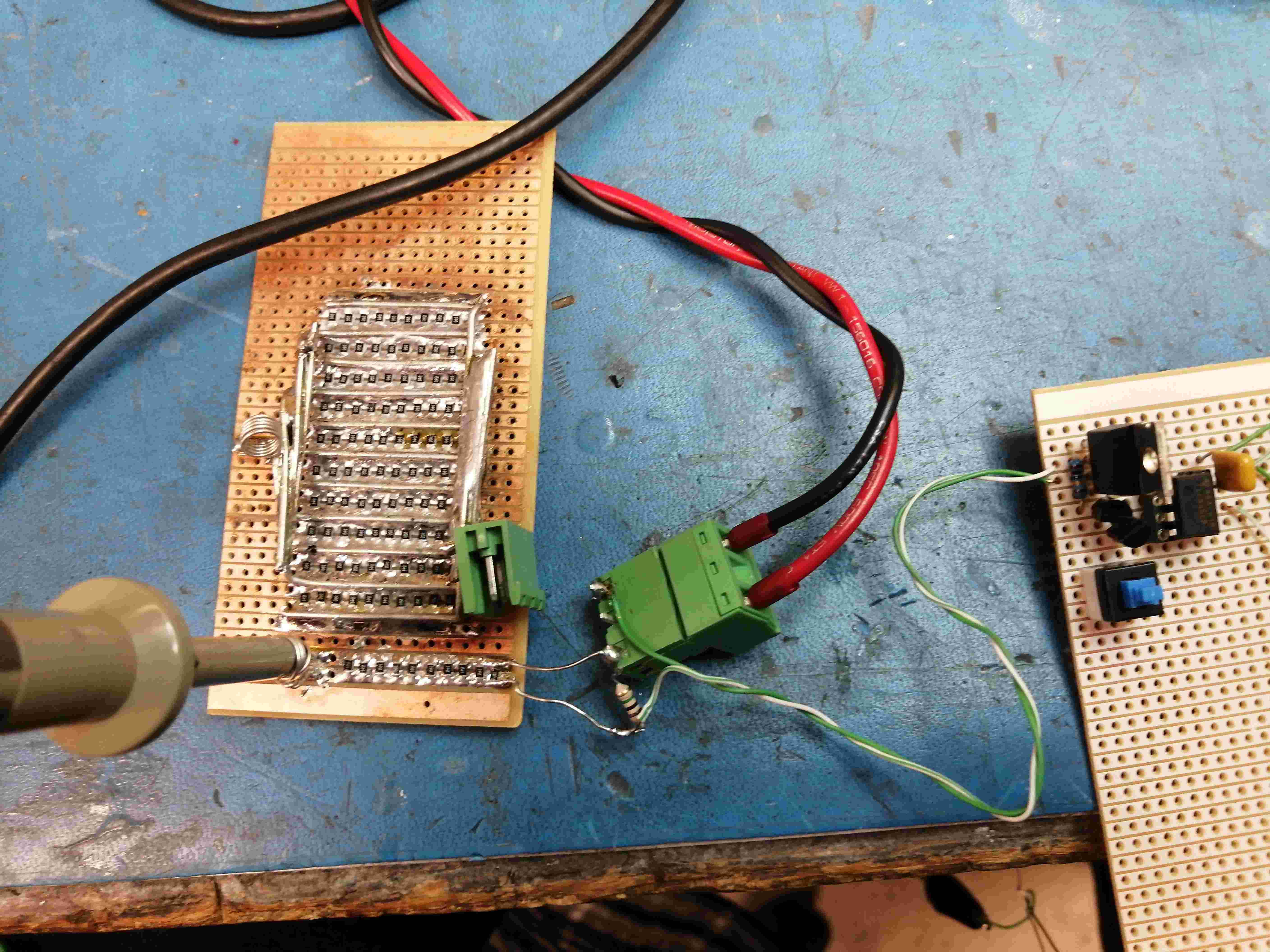
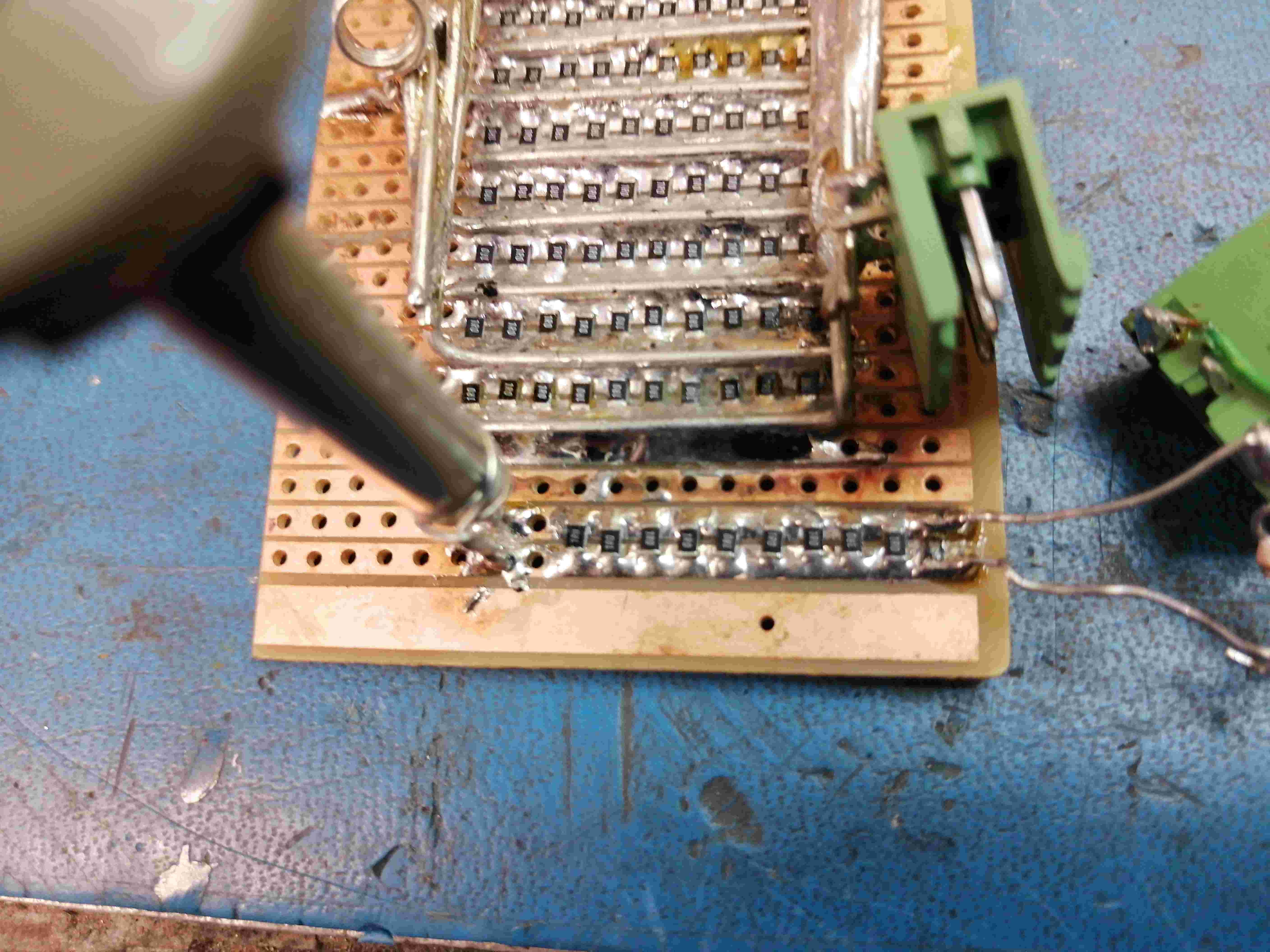
I am making current measurements from a current-limited power supply. I'm currently using a 0.10 Ohm shunt with a X10 scope probe connected directly across the shunt. This connection uses the technique described by both Bob Pease and Jim Williams where the ground connection to the scope probe is bare wire wrapped around the exposed ground metal right at the front of the probe. The probe tip slips into a tiny receptacle right at the shunt.

In other words, the wire lengths between the probe and the shunt are as short as I can possibly make them.

Scope is a Tektronix THS720P. Probes are, I think, P119 Tek probes (X10 only). That said: I have lots of different Tek scope probes available for use if advisable.

The shunt is 10- 1.00 Ohm 1206-size resistors in parallel using a piece of Veroboard (stripboard). Very small, as low inductance as I know how to make it.

I have also made a similar shunt that uses 100 pieces of the same resistors for use when I can use it.

I've got two problems.

  1. I am losing 90% of the available signal because of the X10 probe. If I was able to use a X1 probe, I could either go to a 0.01 Ohm shunt or get better resolution on the wave forms.

The scope probe is connected right at the shunt.

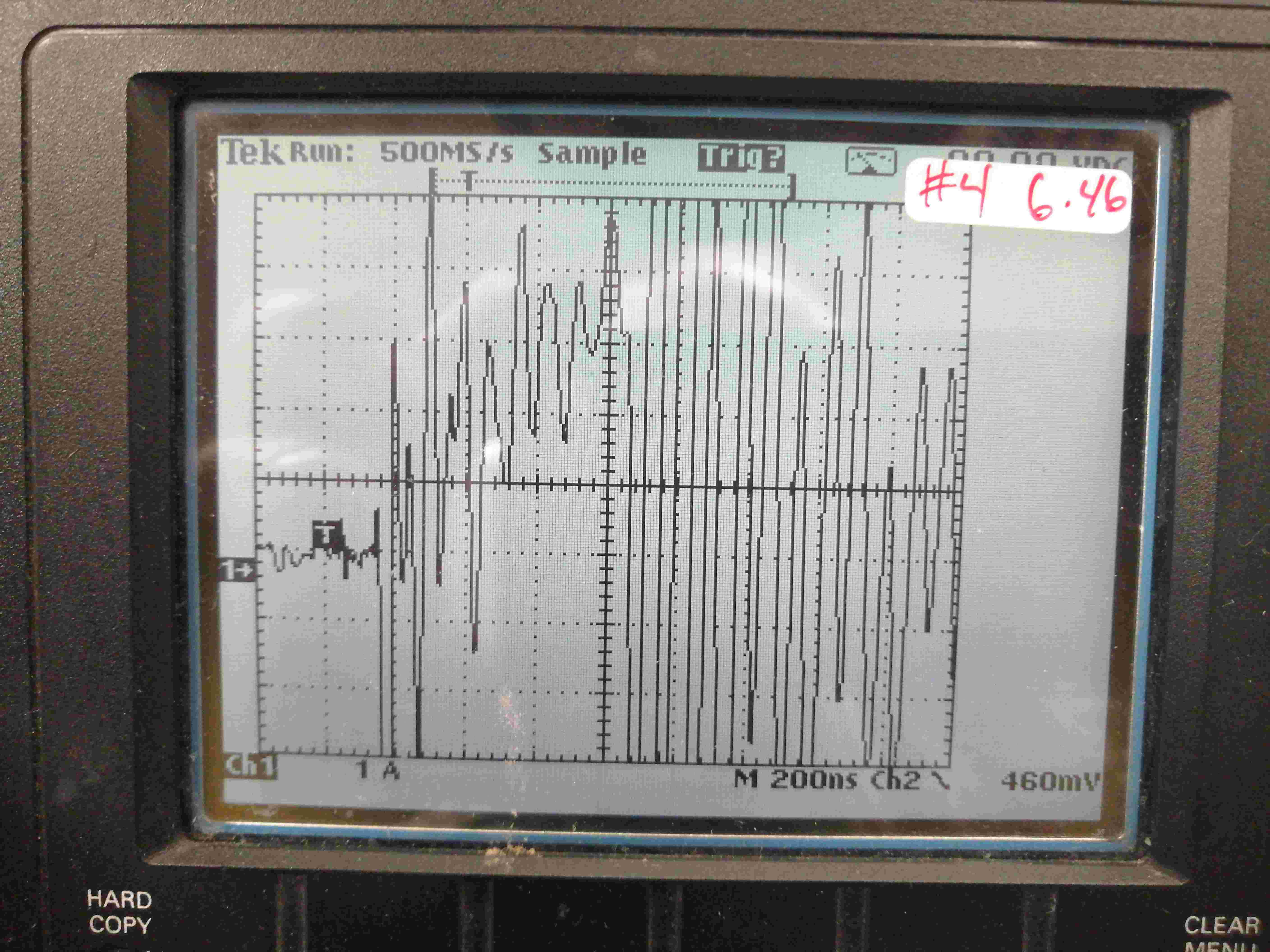
  1. I'm getting a lot of ringing in the wave forms. Just moving wires around changes the ringing, suggesting that I have measurement technique problems.

For example, connecting the DMV connections of the Tek 720P scope causes the ringing to get worse.

I'm asking for suggestions on how to use (or fabricate) a X1 scope probe and still get good high-frequency response.

Also asking for suggestions on what to do to minimize the ringing that I am seeing.

I have an old Tek scope probe or two where the cable is in great shape but the probe body plastic is disintegrating. I can use those cables as I see fit if anyone has any suggestions.

Should be - is a ramp

The initial portion of the wave form is a ramp with much ringing.

[Edit]

Suggestions / questions were made in regard to the loop area occupied by the current-carrying conductors.

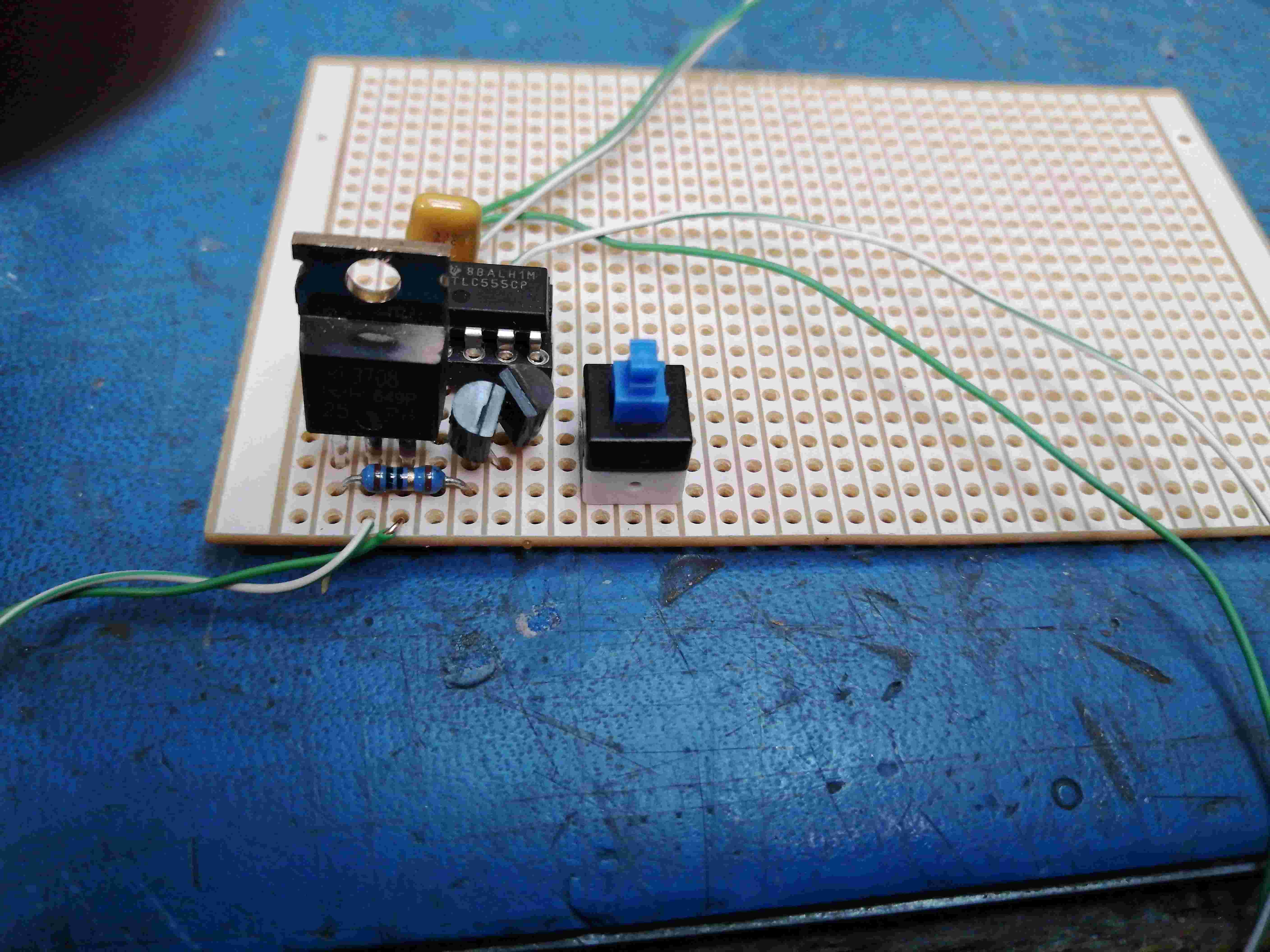
The wires are twisted pair so as to minimize loop area. Please see the photos below.

Interestingly enough: I seem to get better results when the wires are NOT twisted! The ramp is more easily recognized ant there is LESS ringing.

Overview FET Switch Shunt

\$\endgroup\$
6
  • \$\begingroup\$ How long is the unshielded current LOOP PATH in mm in the circuit not protected by a ground plane? \$\endgroup\$
    – D.A.S.
    Commented Oct 21, 2021 at 20:47
  • \$\begingroup\$ I remember that in some cases ..., we added to the connection point a "cylindrical" carbon resistance of 50 Ohm ? ... I even wonder if in some probes, the same "technique" was not also used ? \$\endgroup\$
    – Antonio51
    Commented Oct 21, 2021 at 20:56
  • \$\begingroup\$ This note can help you ... teledynelecroy.com/doc/10x-passive-probes-appnote figure 6. \$\endgroup\$
    – Antonio51
    Commented Oct 21, 2021 at 21:01
  • 1
    \$\begingroup\$ 50 ohm termination. Connect to the shunt "hot" side via 50 ohms (series termination) and switch on the scope's 50 ohm termination (or add 50R across the BNC plug at teh scope end) \$\endgroup\$
    – user16324
    Commented Oct 21, 2021 at 21:07
  • \$\begingroup\$ It does not help to capture a full BW signal on a 150 MHz scope channel with a 0.1 Ohm shunt if the current loop has series inductance signal source has stray inductance even a couple mm of high current into 1nH shunt with a 10Mohm 9.5pF 1.5 mm 10:1 scope probe will cause resonance. You have high series Q with a resonace around 16 MHz. SHow a photo of your current loop setup. The probe capacitance will still load the parasitic inductance. Did you study transmission line theory? \$\endgroup\$
    – D.A.S.
    Commented Oct 21, 2021 at 21:45

1 Answer 1

0
\$\begingroup\$

If you know the impedance of your 1:1 probe coax is not 50 Ohms but a low capacitance type that Tek uses such as 75 ohms (or higher) then you would use a series R of 75 Ohms series input and same on DSO as a load with a 2:1 scale factor.

The DSO 50 Ohm internal terminator is convenient, but this will cause some ripple in the coax response from mismatch at 1/4 wave multiples >~ 100 MHz. So it may be better to use a BNC "T" on the DSO and insert a thruhole 75R like a jumper, bridging the BNC centre and barrel. (*)

For measuring DCDC ripple voltage , you can use the same 1:1 coax probe method with < 1cm connections to gnd. You can also use 50 Ohm Coax with on-board SMA socket or similar. But you must use a series Cap to avoid risk of burning out the 50R load.

So Vdd > low ESR series 0.1uF//1uF > series 50=Rs << coax << DSO 50R shunt. This will give textbook quality waveforms of your ripple with 10kHz to > 100 MHz BW.

Additional info: https://download.tek.com/document/02_ABCs-of-Probes-Primer.pdf This is just the basics. It's more complicated than this.

\$\endgroup\$

Your Answer

By clicking “Post Your Answer”, you agree to our terms of service and acknowledge you have read our privacy policy.

Not the answer you're looking for? Browse other questions tagged or ask your own question.