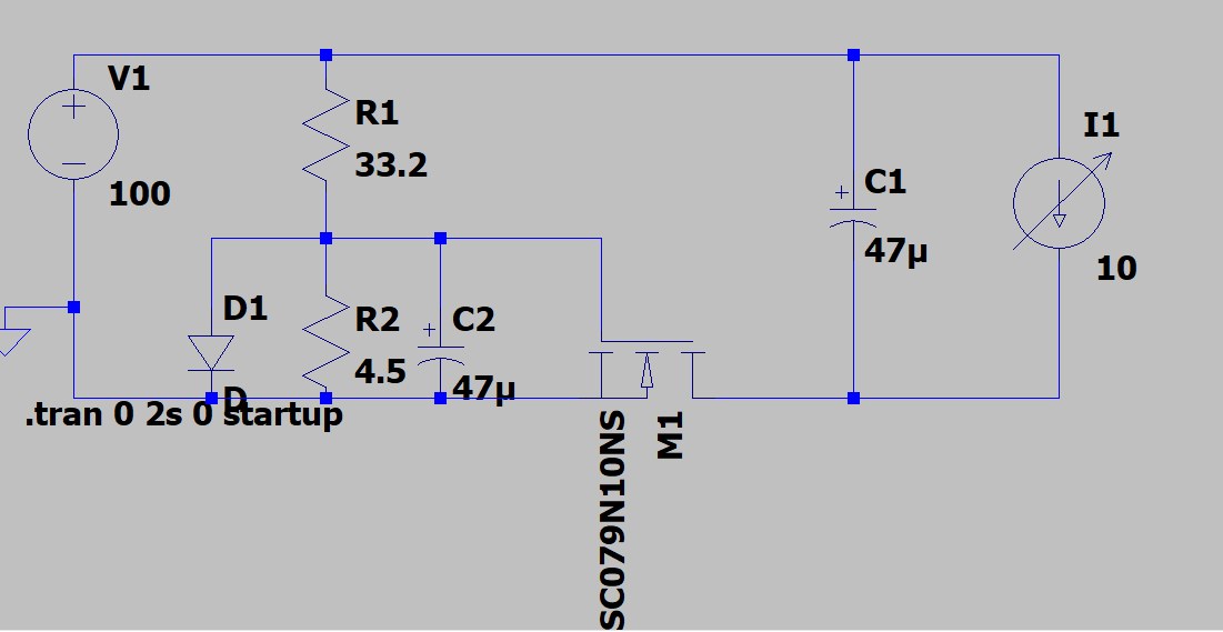
I have a soft start circuit that looks like so:
The load will actually be a synchronous boost/buck converter, and ultimately this could also have an AC source instead of just DC and have a rectifier put inline as well.
The issue is that this works fine (and the inverse with an PMOS works fine too but obviously more loss) dropping the surge from 240A initially to 3-4 amps. But this is just a simulation. I'm actually building several circuits that will have voltages anywhere between 40 VDC and 600+ VDC. (1 solar panel at low output versus 10+ in series at high output all of which need to be supported.) This is also an issue for the battery which could be anywhere from 40 VDC to 460 VDC (wide battery support range) so powering this off the battery instead of the solar side isn't really an option either, and ultimately we need to be able to support either battery or solar powering which I think we have solved.
The AC side of things is straight forward because it's a known 240 VAC within a narrow range so calculating R1/R2 isn't a problem. But for the solar string/battery, because of the wide range, calculating values that work. As an example, using the below, if the V1 goes to 460 VDC then the gate would be getting 55 V which of course generates magic smoke. And if I try and adjust for a middle line there, then I'm still at 23 V on the high side with a 1.7 Ohm R2 and 2 V which will either cause magic smoke on the top end, or won't turn on the gate at the bottom.
My initial solution was to use one of these: High Voltage Range Step Down Buck Regulator to just take the wide range and step it down to a nice 12 VDC for my POC and 6ish VDC for the full scale product that will be using GanFETs or SiCFETs (experimentation is required and my be chosen for us if we go up more than 600VDC on the solar series array support) for the synchronous full bridge. That works fine, except the issue there is that I'm worried that it's going to get hammered on inrush, even if I put it in parallel. (i.e. it would go in the place of R1/R2/D1/C2 and I'd use it to power the gate drivers and the inrush control fet in the final design.)
Once I'm past handling the inrush current, the rest works just fine.
So my questions are:
- Are my worries founded about the circuit in parallel to power the gate?
- If so, how do I power the gate in such a circuit for in rush when the input voltage can be so variable? I'm not opposed to using a good PMOS if I can find one with low Resistance if I can not cook the gate with too high a voltage differential.
I'm really trying to avoid having something like an LTO/LiION battery inside this thing that powers the gate and has to recharge too, just to handle this problem.

