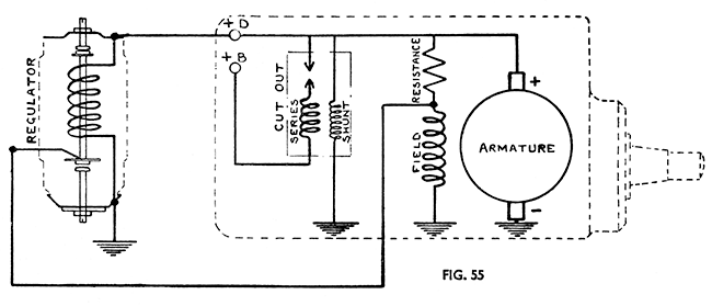
First, refer to the Miller charging system diagram, here: https://dunhackin.com/index.php/velocette-documents/mac-manuals/28-rigid-frame-mac-service-manual/310-miller-lighting-set

Let’s break down (so to speak) how the Miller regulator works.
At rest, the regulator contacts connect the +D to field (solenoid is ‘up’).
When the engine is started and at low RPM (idle, say):
- field coil gets its current from the armature through both the load resistor (about 7 ohms) and the regulator. The field current and field flux increase.
- as the the voltage increases to the setpoint, the regulator solenoid opens the upper D+ contact. This decreases the field current to only that provided by the resistor.
So at low RPM the solenoid will cycle field between D+ and open. This will regulate to a low-limit voltage.
Now increase the RPM:
- a further increase in voltage pulls the solenoid down more and closes lower contact, shorting out the field coil through GND. The field flux and current decrease.
- as the voltage drops again, the solenoid de-energizes and the contacts open.
So at high RPM the solenoid cycles the field coil between GND (short) and the resistor. This will regulate to a high-limit voltage.
Either way, the regulator solenoid is 'buzzing' back and forth, chopping the field coil drive to maintain the voltage by setting an average field flux.
Finally, the battery overcurrent / undervoltage cut-out isn't part of the regulator; those are done inside the generator itself. This is a bit different than the normal old-school car ones that do all three (that includes the Bosch VW one.)
At any rate, seems like it could be possible to make an electronic version that watches the voltage and has that same low-limit / high-limit behavior.
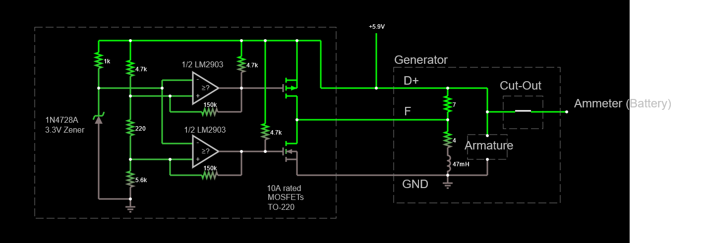
Here's an initial try at doing just that (simulate it here):

The output voltage is compared to a reference (3.3V zener) with two comparators, which drive two big TO-220 FETs. Using two comparators allows adding a 'dead band' between the two trip points, modeling how the solenoid would behave, and also prevents turning on both FETs at the same time. There's some hysteresis (snap-action) provided on the comparators to reject noise.
The sim has a voltage slider so you can see how it behaves in response to the dynamo voltage. In the sim it’s set to regulate between 5.8 and 6.4V with about a 200 mV dead-band between the two. This is tighter than what the mechanical regulator did, and at a lower voltage limit (the Miller regulator is set for between 7.5~7.9V). You can adjust the regulator by modifying the resistor values to change the trip points.
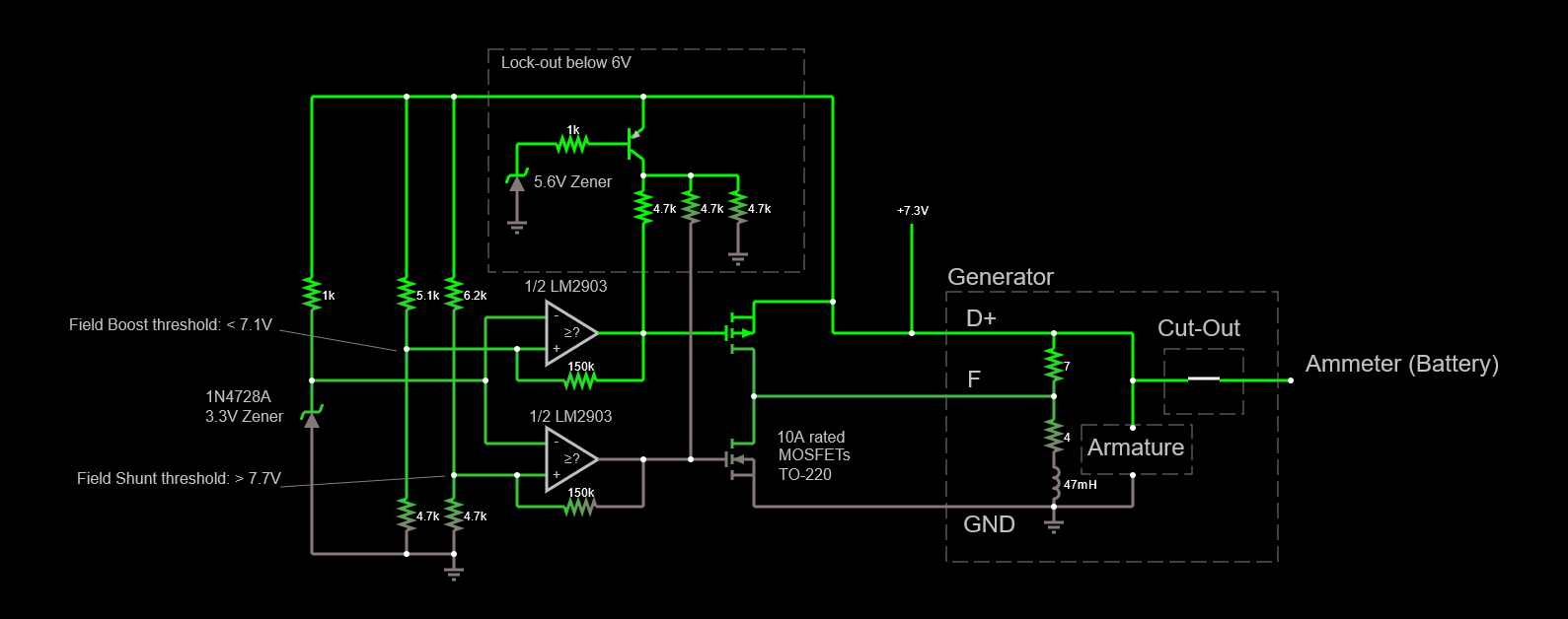
Here's an improved version that fixes a start-up issue and uses lead-acid battery voltages so that the dynamo's cut-out can work (simulate it here):

This is set for lead-acid battery thresholds (7.2V nominal charge, 7.7 max), and adds an undervoltage lockout that forces the upper FET on and the lower one off until the voltage is high enough for the comparators to work. The comparator thresholds are set independently here so they're easier to adjust if needed. PNP transistor is 2N3906 or similar.
Were you to construct this, all the components are through-hole and easily solderable. I do recommend mounting the FETs to a heatsink, and that everything be made robust enough to stand up to vibration and heat. Consider potting the whole thing in RTV silicone for example.
Finally, the Supercap stack should be increased to 3 to have more margin for generator ripple and noise. I’d also consider blocking the generator-to-battery path with a diode, just to be safe.
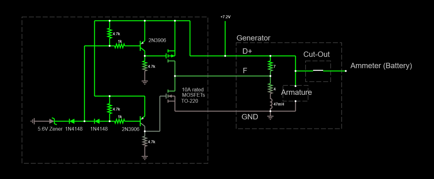
If the comparator still has startup issues at low voltage, here's a design that uses only discrete parts (simulate it here):

This setup uses a 5.6V Zener and silicon diodes to set two trip points: 6.6V (Zener + diode) for charge and and 7.2V (Zener + 2 diodes) for high-limit. The voltage should stabilize between those two, being high enough for the cut-out to close without overcharging the battery. It's a bit kinder to the lead-acid battery than the Miller regulator, which set a max float charge of 7.5~7.9V.
Unlike the comparator version, this isn't resistor adjustable nor does it have hysteresis. You can adjust the trip points by adding additional diodes in series (each one will add 0.6V to the trip point) or using a different Zener.
I show the PNP transistors as 2N3906; they can be any common switching type.


