1
\$\begingroup\$

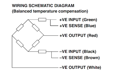
I'm designing a full Wheatstone bridge for measuring the bending strain in a steel bar. I have a circuit available to me that uses an ADS1232 to measure the output of the wheatstone bridge. When looking at loadcells online I see that they have 6 cables (sense + and sense-). From what I understand, these cables go to the excitation points of the wheatstone bridge and allow the circuit to measure the voltages, which cannot be done with the excitation cables themselves as they would have a voltage drop due to the much larger current draw. The sense cables do not draw much current as they are going into an opamp. Is this understanding correct?

Example wheatstone bridge with 6 cables

I also don't understand why there are two resistors in series with the bridge. I've read online that they are for temperature compensation, but nothing goes into more detail then that.

If I was to attach strain gauges onto a steel beam, would I need those resistors? and where would they go, and with what value? Would I need anything apart from the 4 strain gauges in a full bridge configuration with sense cables going to the REF_P and REF_N terminals of the ADS1232 IC?

\$\endgroup\$
1
  • \$\begingroup\$ One reason to add those two resistors is to lower the differential voltage. An HX711 for example maxes out at 20mv (or 40mv or 80mv). You may need them to keep the differential within range depending on what strain gauges you are using, how well balanced they are and what the range of your ADC converter is. \$\endgroup\$ Commented Dec 12, 2021 at 0:52

1 Answer 1

0
\$\begingroup\$

Strain gauge elements made of nickel have a positive temperature coefficient of about +0.6% per °C at room temperature. If you energize the bridge with a constant current, the "gain" of the bridge will have that coefficient as well since the percentage change in resistance is pretty much constant with temperature.

By energizing the bridge with a constant voltage and adding resistors that have a similar temperature coefficient, the output of the bridge a reasonable voltage (usually 2.5 to 10V) can be used and the output at off-balance will be more constant with temperature.

Because there are 4 wires, each with resistance, connecting the bridge to the measuring instrumentation, we would like that resistance to have minimal effect on the performance. By measuring the voltages (the difference is what matters) using the sense wires we can either compensate for the resistances or, more alternatively, drive the "input" wires such that the voltages at the strain gauge are fixed values, say with a couple of op-amps.

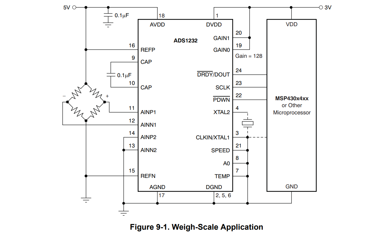
Here is the typical application for the ADS1232 from the datasheet:

enter image description here

This circuit assumes the bridge can be powered directly from +5V and there is no compensation for the wire resistances (no sense and force wires). If you want to compensate, you would either have to add that circuitry or find some way to use the ADC to measure those voltages and compensate digitally (there are two unused inputs). You can compare the bridge resistance with the wiring resistance to see if that's necessary in your case.

The typically application shows few additional components but if there is a cable attached you'd want to add protection and filtering, which would help with the anti-aliasing filtering.

Commercial instrumentation strain gauge signal conditioners are often galvanically isolated, because of the low level of the signals and the desire for the installation to be trouble-free.

\$\endgroup\$
2
  • \$\begingroup\$ Thank you for the great explanation! The effect of temperature on the strain gauge elements is somewhat compensated by a full bridge setup (4 strain gages, no balance resistors), from what I understand, to further compensate you are saying these thermisters have an opposite temperature coefficient, and I could compensate for the temperature more by using them? I assume they will also need a trim potentiometer in parallel to change the gain of this compensation. \$\endgroup\$
    – mosfeta
    Commented Nov 18, 2021 at 4:20
  • \$\begingroup\$ The resistors have the same temperature coefficient, so the result is ratiometric to the excitation voltage at the bridge itself. Beyond first-order compensation (offset and gain) probably requires some proprietary trimming. \$\endgroup\$ Commented Nov 18, 2021 at 4:22

Your Answer

By clicking “Post Your Answer”, you agree to our terms of service and acknowledge you have read our privacy policy.

Not the answer you're looking for? Browse other questions tagged or ask your own question.