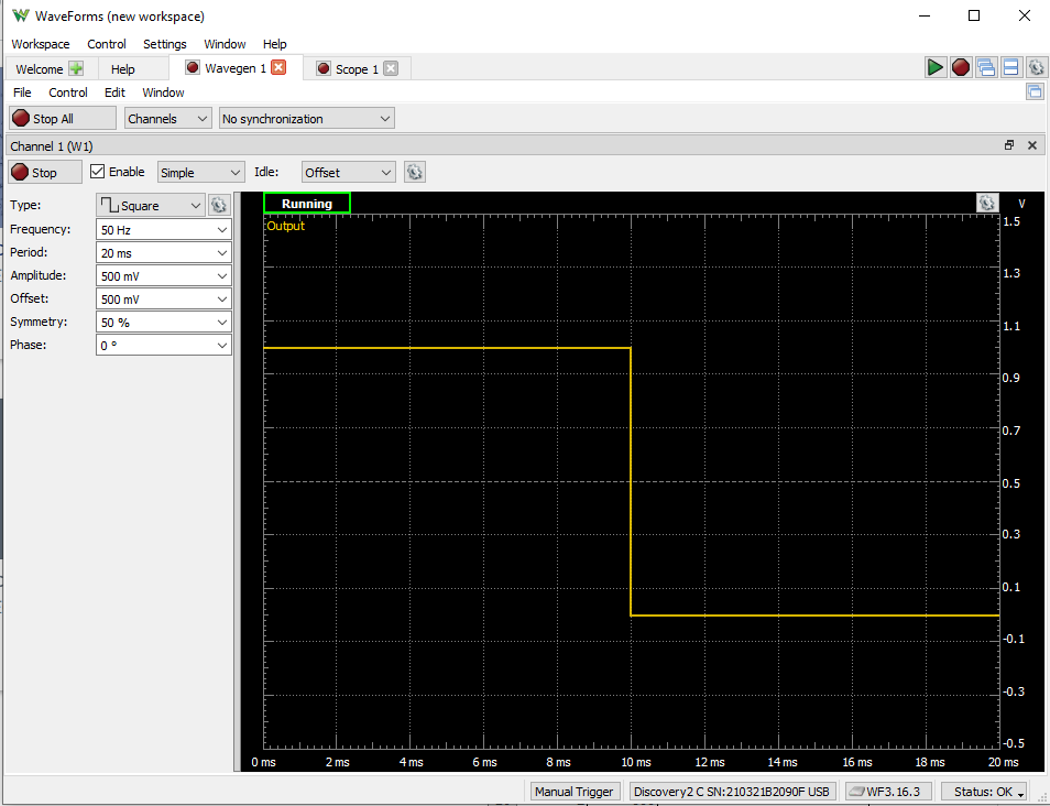
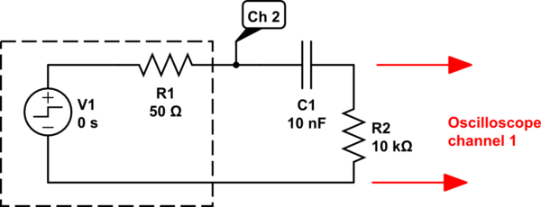
I have a lab for a circuits class and in it we are building an RC series circuit with a square wave input. I am using a function generator to produce a square wave at 50Hz, period = 20ms, Amp = 500mV, Offset = 500mV. I am to measure the output voltage across both the resistor and capacitor.
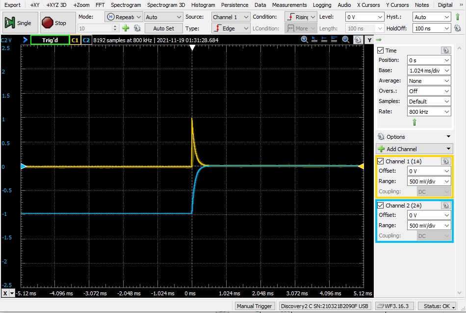
The resistor is 10k-Ohm and the capacitor is 10nF. I know at T = 0 the resistor drops all the voltage and the capacitor drops effectively none, and that over 5 TC the capacitor charges and the current through the resistor lowers. So the graph for the resistor should be a jump to source voltage then taper off to 0V while the capacitor should start at 0V and ramp up to source. However, When I plug in my O-scope, I am getting the resistor behaviour as expected, and the shape of the capacitor waveform is as expected, but starts at -1 V and ramps to 0V. So it looks like on the O-scope that at 5TC neither component is dropping any voltage.
I have read some previous similar questions and applied some of the solutions found there to no avail, such as: I have checked for DC coupling and have verified the circuit is getting the input by using the O-scope to check the function generator output directly, as well as measuring the component voltage with a Fluke.
How do I get the capacitor to show starting at 0V and ramping to 1V?
Here is the input from the function generator:

Here is the output measured by the O-scope:

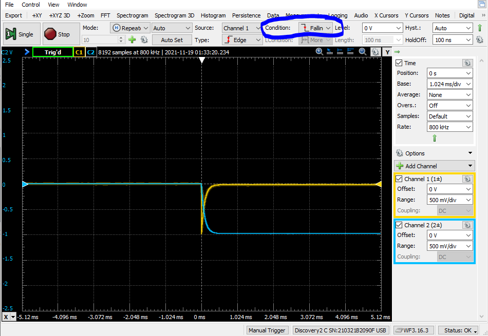
If I change the condition to falling edge, the waveforms overlap in a behavior mimicking what I anticipated, but goes from 0 to -1V, which I don't understand since the input voltage is never negative (and when changing the function generator input to a rising squarewave, the O-scope waverforms don't change).


