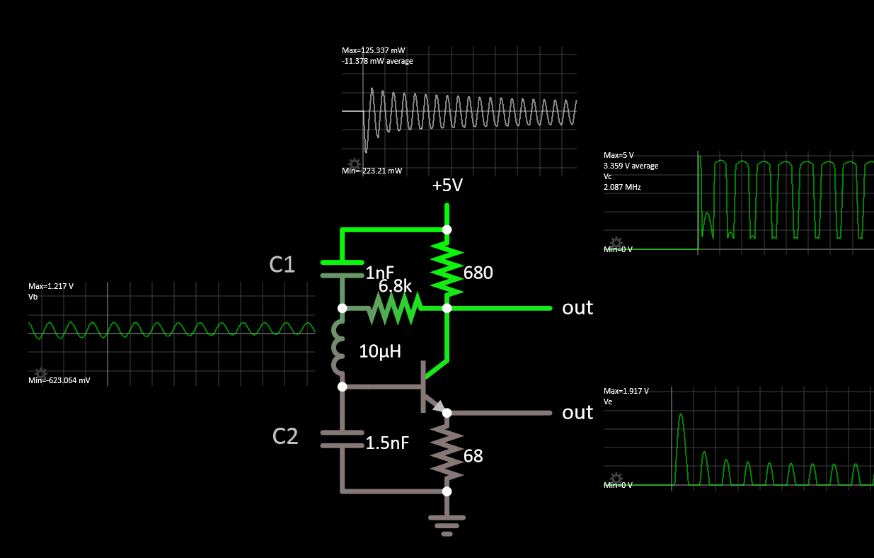
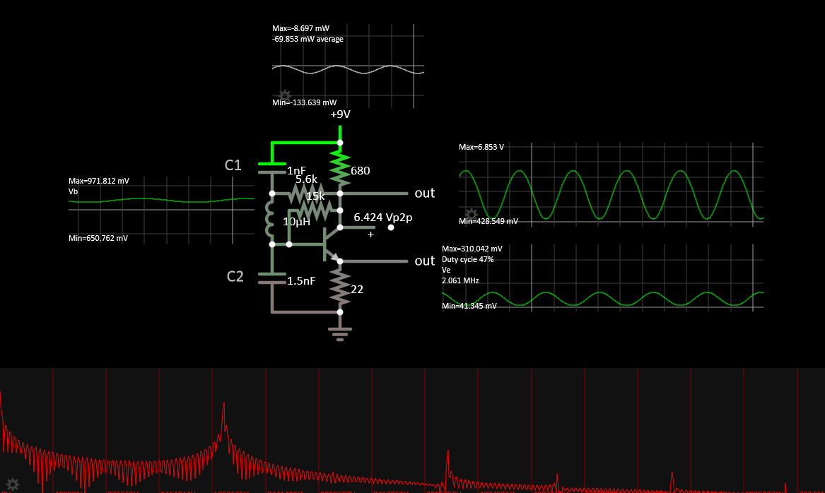
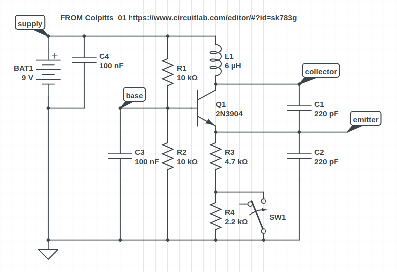
I'm struggling to build a Colpitts oscillator that runs above about 2 MHz. Unfortunately, my understanding of this thing's theory of operation is severely minimal. My end goal is to build a crystal controlled oscillator at 28 MHz for 10 M band (so I'll need it to be stable and clean), but for now I'm running the circuit below (without a crystal).
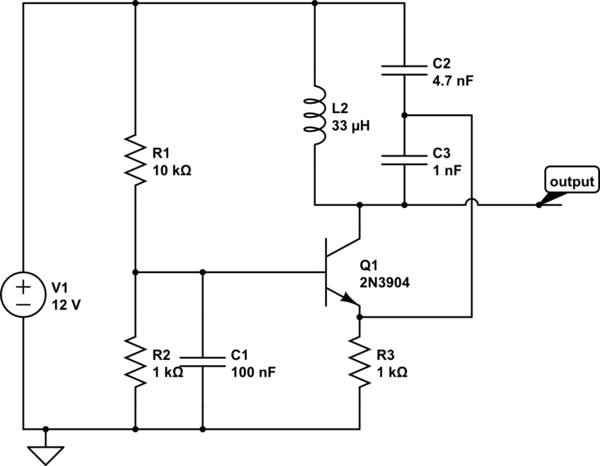
simulate this circuit – Schematic created using CircuitLab
This circuit came from an Analog Devices tutorial I found here: Analog Devices Colpitts oscillator tutorial. It works fine up to about 1 MHz, but the output swing gets smaller and smaller as the frequency goes up. At 1.5 MHz it's giving about 650 mV, but is fairly stable. By the time I get to 2 MHz, oscillation is unstable, and output when it does run is down to about 300 mV.
EDIT: Based on Tony Stewart's comments (see his answer below, and some of my follow up in an earlier edit lower down), I changed the bias on this so the DC collector current is about 8 mA (that was chosen for the 2N5770, but isn't wildly far off the 10 mA target for the 2N3904). This was very effective (though still the circuit as a whole falls short). I can now get intermittent oscillations up to 5 MHz or so (with 1 uH inductor), and it's strong up to about 3 MHz. However, it still fades and quits oscillating sometimes at 5, and clearly that's nowhere near my target of 28. So, I would like to understand the feedback of this system better if anyone can help me with that (and anything else that you think might be relevant).
Note: The reason that I'm looking at this configuration specifically is because I know how to add a crystal to it directly. (See the ARRL handbook version noted below). If you think I should use some other configuration, it would be very helpful if you can show me how to add a crystal to the circuit after I tune up the LC network first.
I found that with a 2N2222 it wouldn't run at 1 MHz, but with the 2N3904 it is better. I also tried a 2N5770 (Ft around 900 MHz) and that gives just a little more output, but still won't go past about 2 MHz.
So, part one of my question is how does one control the output level of this kind of circuit? I've tried changing several things, but nothing has so far made any obvious difference. Part two is how do I get this thing to run at a useful frequency?
A little extra background: I started with the circuit from the ARRL handbook (see this PDF--it's an older edition than my copy, but the circuit is identical ARRL handbook) It's the circuit shown in figure 9.24 on page 23. However, this didn't start at all at 16 MHz--the "slowest" crystal I have. I modified it by shorting the crystal out and changing the tank but it didn't oscillate at all until I also removed the 1k resistor they show shorting the tank. But, with the 1k removed, and the crystal replaced with a short and greatly modified L&C values for lower frequency, I can make this behave pretty much the same as the above (aside from biasing, it is essentially the same.) They're claiming that either a 2N2222 or a 2N3904 can get this thing to run up to 30 MHz, but that's not what I'm finding.
EDIT:
Following on from Tony Stewart's observations, I have more questions:
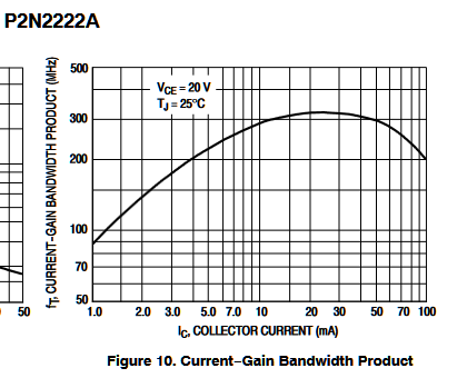
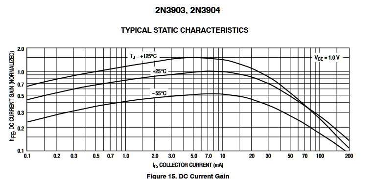
Tony, you said "If you do not operate in the current range specified for Ft= BW then hFE will be reduced In your case by 50%. That is specified @ 20 mA with is the near the max. of the hFE vs Ic curve."
I'm not really understanding this (lack of education on my part). I think you're referring to this part of the datasheet:
But, if this is what you meant, does that mean I should bias this thing for 10 mA? Or am I looking at the wrong thing and/or entirely misunderstanding?
(Another edit...) I see that the 2N2222 does indeed list 20 mA in the same section that I pulled the 10 mA figure from the 2N3904 datasheet. So, I think that I have interpreted your information correctly??
Next you said "You can alter this high current requirement by using more feedback or less attenuation and thus more loop gain to achieve greater than unity for oscillation." Can you tell me where the feedback is in this circuit, I don't understand it well enough (indeed, this is one of the "control" elements I was referring to in the question title). And attenuation? What components are providing that? What do I need to change?


