1
\$\begingroup\$

I am brand new to building circuits, so I apologize if I use the incorrect terminology. I am trying to build an oscillator circuit that will output a Triangle Wave and Square Wave in tandem (trying to dip my toe into building modular synthesizers).

I will try to explain my problem referencing the following pictures:

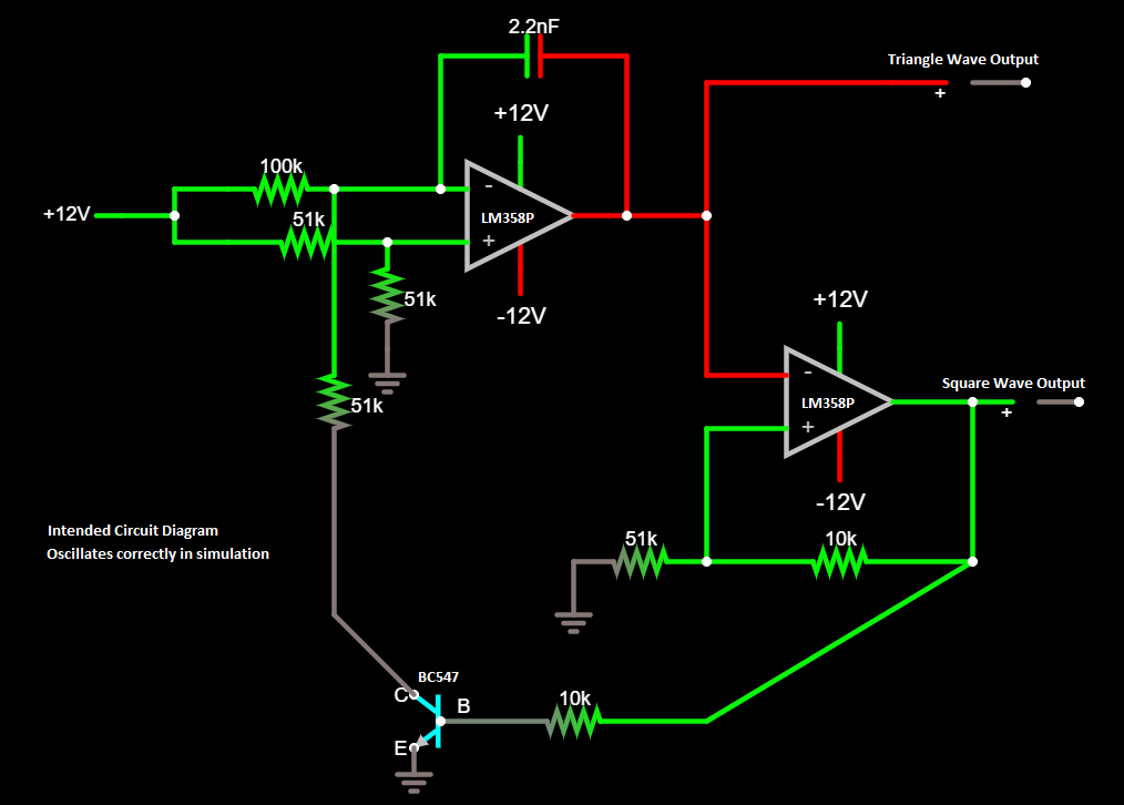
  • Intended Circuit Diagram - The complete circuit I am trying to build
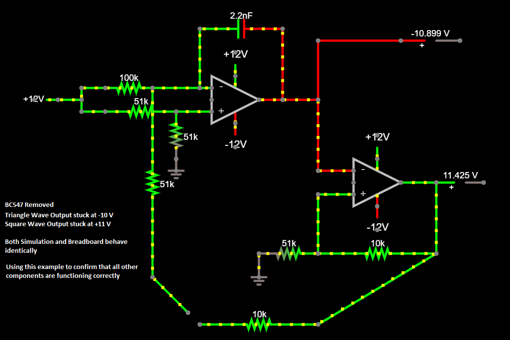
  • BC547 Removed - Removed the BC547 Transistor to confirm all other components are working
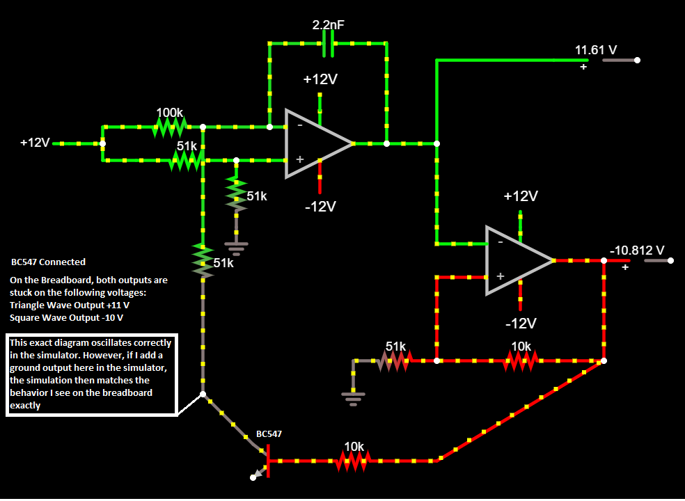
  • BC547 Connected - Re-connected the BC547 Transistor and started seeing inconsistencies

NOTE: I built all simulated diagrams with Falstad Circuit Simulator. The exact circuit I am trying to build can be found at this link. I am specifically referencing the section titled "Oscillator Core".

Intended Circuit Diagram Intended Circuit Diagram

My main problem is that the simulator and my breadboard are showing different behavior when connecting the Transistor (BC547).

I've narrowed my focus to the Transistor (BC547) because if I test the entire circuit after removing this component, everything behaves identically between the simulator and breadboard:

BC547 Removed enter image description here

When re-introducing the BC547, I start seeing inconsistencies between the simulation and my breadboard. In the simulation, adding in the BC547 allows it to start oscillating as intended. However, on the breadboard, my voltage levels remain static (Triangle +11V, Square -10V). I believe I am connecting the transistor with the correct pinout. What's interesting is that I can flip the transistor around and reverse the Collector and Emitter legs in the simulator, and it still oscillates correctly.

I tried to replicate the exact behavior in the simulator, and I found that if I added a ground output to the collector leg of the BC547, the simulation behaved the exact same way as the breadboard.

BC547 Connected enter image description here

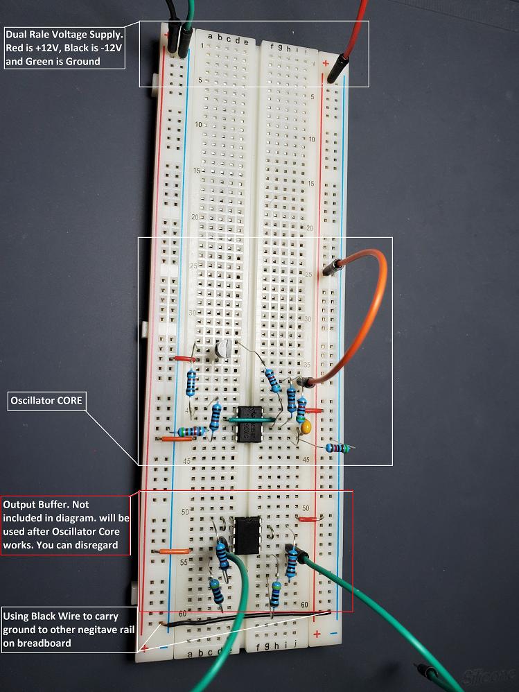
Apologies if I left out any important information. I've narrowed my focus to the transistor in my testing, so I wanted to start there when asking my question. I will gladly provide any other information if needed. I've included a picture of my current breadboard layout below:

enter image description here

\$\endgroup\$
1
  • \$\begingroup\$ From what I see you have swapped the collector with the emitter, You need to rotate BC547 by 180 degrees. \$\endgroup\$
    – G36
    Commented Nov 20, 2021 at 12:36

2 Answers 2

1
\$\begingroup\$

That circuit should work.

You need to measure some voltages to determine the cause of the problem.

That is half the job of being an engineer, to understand your circuit well enough and do the required measurements to correct any issues.

The transistor should be non-conducting with -10V on its base so the integrator should be giving out +11V not -11V.

One undesirable point with the circuit is that when operating from 12v the negative voltage to the base of the transistor will exceed its breakdown voltage (typically about -7V). This should not stop the circuit working but can cause degradation of the transistor.

Edit: Note the comment by @G36. It does look like the collector and emitter are swapped. That would possibly stop it operating.

Note that it might not affect operation, BJTs can operate with collector and emitter swapped but they will have very low Hfe and the base emitter breakdown (now base-collector if swapped) is only about 7V as mentioned earlier.

The base drive from the second opamp will pull the inverting input of opamp1 to a low level through the broken down base-emitter junction. The low level will cause the output to incorrectly be at 11v.

In future when posing questions with schematics please make sure that they have component references, otherwise it makes it very difficult to explain which component is being referred to in an answer.

\$\endgroup\$
-1
\$\begingroup\$

From the comparator's schematic at https://www.ti.com/product/LM358?keyMatch=LM358P, it won't operate when the common-mode inputs are within about 1.6 V of the supply; also, the output won't go to the negative supply -- about 0.7 V above it.

You can see in your circuit that the output of the 2nd comparator is -10.8 V. This is not enough to turn off the NPN BC547.

If you add a 4.7k or 10k between its base and emitter, then it will turn off even with -10.8 V

\$\endgroup\$
2
  • 1
    \$\begingroup\$ The transistor is connected emitter-to-GND, not emitter to -12V, as seen in the picture (green wire to GND bus rail); it's OFF to excess. \$\endgroup\$
    – Whit3rd
    Commented Nov 20, 2021 at 10:03
  • 1
    \$\begingroup\$ indeed it may no longer be off, but in reverse breakdown \$\endgroup\$
    – user16324
    Commented Nov 20, 2021 at 11:52

Your Answer

By clicking “Post Your Answer”, you agree to our terms of service and acknowledge you have read our privacy policy.

Not the answer you're looking for? Browse other questions tagged or ask your own question.