0
\$\begingroup\$

I have to control 10 brushed DC motors from a microcontroller. I am using an H-bridge driver for each motor which controls the speed (PWM), direction (High/Low), and enable/disable.

So, for each motor I need to use 3 pins (10 motors, 30 pins) and I just have 2 PWM pins and 4 GPIO pins on my microcontroller.

Can you suggest some H-bridge driver ICs that let me control all the motors with fewer pins? It's ok to run the motors one by one i.e. at any instant, I want to run max. 2 motors.

\$\endgroup\$
7
  • \$\begingroup\$ Have you looked into I2C or an I/O expander? \$\endgroup\$
    – winny
    Commented Nov 20, 2021 at 9:24
  • \$\begingroup\$ I wonder if you have enough current available in your power source. \$\endgroup\$
    – Krauss
    Commented Nov 20, 2021 at 9:36
  • \$\begingroup\$ You could also put a multiplexer and adress the motors one by one. You would need three pins for data and four pins to adress them. You could put several in parallel. \$\endgroup\$ Commented Nov 20, 2021 at 9:36
  • 2
    \$\begingroup\$ I do not have that many pins on my microcontrollers Well, how many have you got? Please edit your question to detail what you have in all places, not what you haven't. \$\endgroup\$
    – TonyM
    Commented Nov 20, 2021 at 9:50
  • 1
    \$\begingroup\$ I would use 1 MCU per motor and then connect them to one master MCU through CAN. \$\endgroup\$ Commented Nov 20, 2021 at 10:55

2 Answers 2

0
\$\begingroup\$

If you can run multiple motors simultaneously at the same speed and direction, then you can connect all of the PWM pins to the single MCU PWM pin. Also connect together all of the direction pins and connect them to one of the MCU GPIO pins.

2 of the remaining 3 GPIO pins can be used to control a serial in, parallel out (SIPO) shift register such as the 74HC595. This IC is an 8 bit shift register, but we'll see later how they can be daisy-chained to provide as many parallel output bits as you need. If you chain two of them, then you'll have a 16 bit output shift register, but you can use just the first 10 outputs and ignore the other 6.

In essence, a SIPO shift register takes bits one at a time on the input (i.e. serial communication) and presents them all at once on separate, parallel outputs. Typically there is a data input pin and a clock pin. On the 74HC595 the data pin is 14 and the clock is applied to pin 10. Every time the clock pin is cycled, a new bit is accepted at the data input, and all of the existing bits are shifted through the register one output at a time. The link above has animation which explains it pretty well.

So, we connect each output to the enable pin of one of the motor drivers, then start shifting zeros and ones into the shift register until the outputs have the right combination of motors enabled. Then, you stop cycling the clock pin and start the PWM. You could also use the one remaining GPIO pin to control the RCLK pin as a latch as explained in the link above.

Daisy chaining is simple. With two (or more) 74HC595, connect the "function" pins (VCC, GND, clock, latch, clear, etc.) to all of the 74HC595's. Feed data bits into pin 14 of the first one. After clocking in 8 bits, the data will start spilling out pin 9. So, connect pin 9 (output) of the first IC to pin 14 (input) of the second. The second IC will effectively pick up where the first left off and serve as the 9th through 16th bits. There's a good explanation it here.

\$\endgroup\$
0
\$\begingroup\$

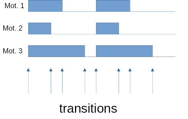
I can imagine to use a 10bit shift register (serial input type) with latching function that will hold the high/low state of PWM pulse of each motor. But this would take a lot of computing capability of MCU, mainly if you choose a high freq. PWM, because you would have to write a new data to shift register after every transition. (see picture)

For PWM frequency less than 1kHz it should not be a problem (using 100kHz SPI or so).

enter image description here

For direction and enable control use another shift registers.

\$\endgroup\$

Your Answer

By clicking “Post Your Answer”, you agree to our terms of service and acknowledge you have read our privacy policy.

Not the answer you're looking for? Browse other questions tagged or ask your own question.