2
\$\begingroup\$

Our main purpose is create the transfer function of a transformer, and we want that for a resonance frequency higher than 1 MHz for our LLC transformer in an LED project.

https://www.omicron-lab.com/fileadmin/assets/Bode_100/ApplicationNotes/Transformer_modelling/App_Note_Transformer_modelling_V_2_0.pdf

We apply this document's processes for this goal. We have already calculated and measured R1, Ll1, Lmag1, Gain, R2, Ll2, C12, C1, C2, Lc1, and Lc2, but we have seen that our C1 and C2 capacitance values are negative.

In which situation can capacitance values become negative and why does this happens?

Without these calculations, when I measure the transformer capacitance from an LCR meter, the result is also negative. What is the reason for that?

\$\endgroup\$
6
  • 4
    \$\begingroup\$ A negative calacuated capacitance often means that your calcuation frequency is too high, and that it's infeasible to operate your present structure at that frequency. Resonance > 1 MHz will be difficult to achieve, you may need to choose a different transformer structure than the one you have at the moment. If you're using an LCR meter, then a negative capacitance measurement means it's measuring a positive inductive reactance. \$\endgroup\$
    – Neil_UK
    Commented Nov 26, 2021 at 14:58
  • \$\begingroup\$ Did you just bought a transformer? Or did you design it? Well... if you want to model the transfer function precisely without the transformer itself (only with the design) you can try some approach like this researchgate.net/publication/…. \$\endgroup\$ Commented Nov 26, 2021 at 15:40
  • \$\begingroup\$ Dear Neil_UK, firstly thank you four quick answer. We dont calculate capacitance negative at not only high frequenices but also at low. And 1MHz is a utupion goal for now, ı mean that we try to increase resonance frequency as much as we can. And we did not measure it not only from LCR meter but also we use BODE100 device for high accuarry. \$\endgroup\$
    – user300880
    Commented Nov 26, 2021 at 16:47
  • \$\begingroup\$ Dear Luiz thank you for quick answer, before starting modeling our main transformer , we design basic transformer that having turn ratio 2:1. And we did our measurment on it. And ı am gonna check your source. Thanks \$\endgroup\$
    – user300880
    Commented Nov 26, 2021 at 16:51
  • \$\begingroup\$ What makes you think a high frequency LLC will work more efficiently into low ESR caps and low ESR LEDS with higher reactance L? You need to test LRC at 100kHz minimum \$\endgroup\$
    – D.A.S.
    Commented Nov 26, 2021 at 21:02

1 Answer 1

1
\$\begingroup\$

Can help in LLC application.

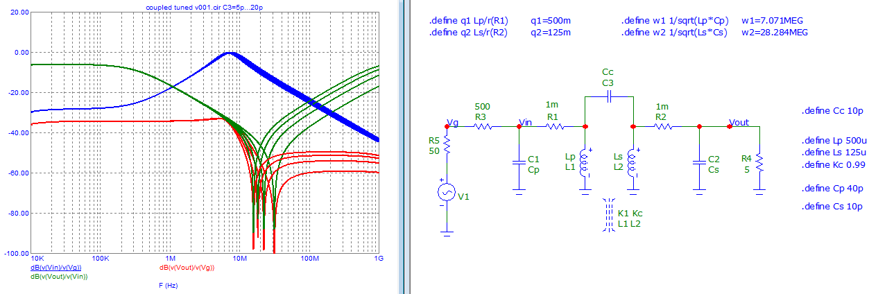
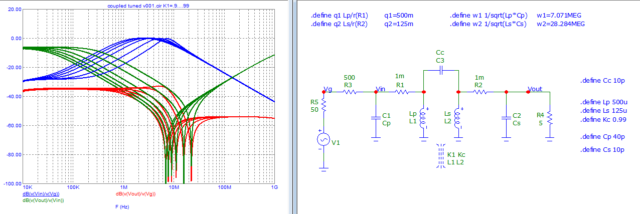
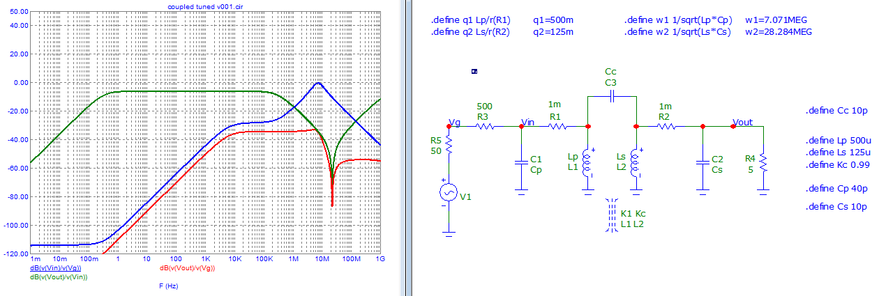
Coupled tuned circuits (magnetically and capacitively) are a bit difficult to be identified.

Some examples of behavior. https://archive.org/details/mc12cd_202110

They can be useful in understanding (or identifying) the role of some components or parameters.

Global enter image description here

Head capacitor change enter image description here

Inductive coefficient coupling change enter image description here

\$\endgroup\$

Your Answer

By clicking “Post Your Answer”, you agree to our terms of service and acknowledge you have read our privacy policy.