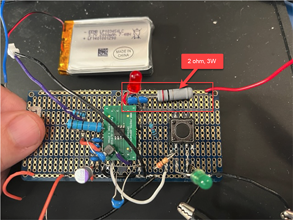
I'm working with a surface mount IC in an SOP-8 package. The IC handles LIPO battery charging at up to 2.1A. It also provides an integrated boost converter with 5V, 2.4A output. Below is an image of a prototype I built that works fine using through-hole components.
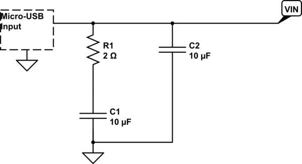
Now, I want to rebuild this circuit with all surface mount components which are as small as possible on a PCB. In the example circuit shown in the IC datasheet includes a 2 ohm resistor in series with a capacitor on the USB charger input power rail, the resistor is shown as R1 in the schematic. The "VIN" in the schematic represents the IC power input at the #1 pin.
The question is around the resistor R1. Firstly, I'm not sure I even need to use it? Is the purpose of this resistor just to drain the bypass capacitors? Secondly, if best practice would be to use the 2 ohm resistor here, what is the appropriate power rating which I must choose?
The voltage source will be a standard consumer-grade 5V ac/dc converter with 1A to 3A output, going to a micro-USB input.
In the prototype shown in the picture, I used the large through hole resistor rated at 3W, and it seemed to work fine, at least in the runtime testing as long as 8hrs, it never got hot to touch.
In moving to surface mount components, 2ohm resistors with such high wattage ratings are both large and expensive. I'd prefer to eliminate it due to PCB size constraints and cost.

simulate this circuit – Schematic created using CircuitLab

