1
\$\begingroup\$

I've got pretty quick question as a beginner in STM32 MCUs. I design my own PCB board for STM32F103C8T6 uC with a couple sensors (connecting via SPI and I2C). I want to include also an USB connector in my design to power on board with it and to try to connect with uC via some serial terminal like for example Tera Term using USB. In design document from STMicroelectronics called "USB hardware and PCB guidelines using STM32 MCUs" is said, that F103C8T6 series need pull-up resistor on a DP (D+) line to 3.3V (because this series don't include internal pull-up resistors). Here's some image from this document: enter image description here

But I found also a schematic for STM32F103C8T6 so called "Bluepill" Board, that I also use and here it looks like this: enter image description here
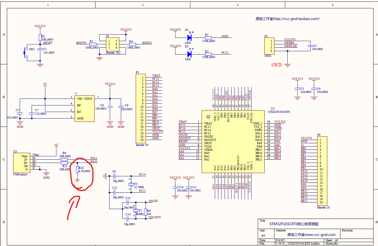
So here's a 4.7K pull-up resistor connected directly to 5V. I am confused about that, because I couldn't find any information about doing that this way, so I would like to ask you if you had any experience in doing this USB connection first or second way, because I am pretty confused and don't have any experience in it yet. The second way with 4.7K and 5V seems much more comfortable, but I dont't know if it will work, because as you can see, the schematic seems to not be from official source, so I don't if I can trust it. I would be very grateful for any guides from you.

\$\endgroup\$
2
  • \$\begingroup\$ I don’t know where you got your bluepill circuit but mine had 1.5k which is the official value. Be wary of dodgy circuits on the interwebs. \$\endgroup\$
    – Kartman
    Commented Dec 11, 2021 at 11:58
  • \$\begingroup\$ Thanks for the reply, but was this pull-up resistor connected for good to 3.3V power supply or to, for example. GPIO Pin, which you had to set as Output first (to supply it with 3.3V), before making connection via USB to PC? \$\endgroup\$
    – ABC
    Commented Dec 11, 2021 at 12:54

3 Answers 3

2
\$\begingroup\$

The Blue Pill schematic is wrong and hopefully it does not damage anything. The pull up should not be to 5V and it should not be 4k7 either. There are multiple other issues in the Blue Pill schematic that are not in line with official suggestions from the MCU manufacturer. Don't trust anything you have not verified yourself to be true.

Another thing is, do you really want the resistor to be always connected to 3.3V, or do you want to control it via software when it is ready to communicate with USB. Tying the resistor directly to a supply voltage will signal the PC that it is ready to enumerate immediately. This could be the source of USB enumeration problems with the Blue Pill that people are having.

\$\endgroup\$
2
  • \$\begingroup\$ So if I understand correctly, should I connect that pull-up resistor to, for example, STM32 GPIO, and configure it as Output to supply it with 3.3V only before I want to use USB to transmit data? \$\endgroup\$
    – ABC
    Commented Dec 11, 2021 at 12:47
  • \$\begingroup\$ That sounds like a good plan. \$\endgroup\$
    – Justme
    Commented Dec 11, 2021 at 13:10
2
\$\begingroup\$

The USB lines on STM32 work at 3.3V logic. Its wrong to pull it up to 5V. Check the [Application note AN4879, page 14.][1] The DP is pulled up to 3.3V logic through a 1.5k resistor.

\$\endgroup\$
1
\$\begingroup\$

You will find all the detail for USB DP connexion described by stmicroelectronics with nucleo board for exemple.

here are the schematics

here is the BOM

Then you unzip files, see the schematics in MB1136.PDF page 3/4 and the BOM component in the excel files

\$\endgroup\$
1
  • \$\begingroup\$ Thank you so much. \$\endgroup\$
    – ABC
    Commented Dec 13, 2021 at 18:42

Your Answer

By clicking “Post Your Answer”, you agree to our terms of service and acknowledge you have read our privacy policy.

Not the answer you're looking for? Browse other questions tagged or ask your own question.