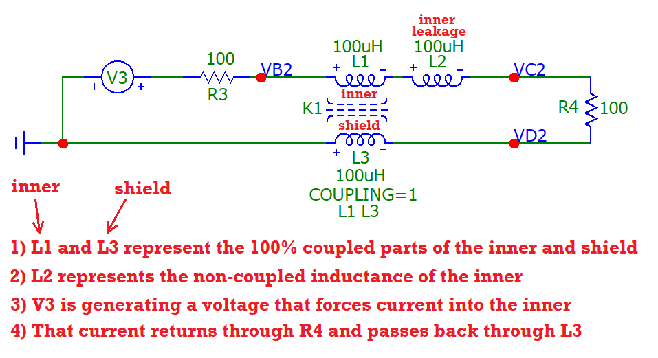
The standard way to drive a signal through a coaxial cable is to have the shield grounded, and a single-ended signal applied to the center conductor.
(Throughout, I will assume that \$R_{term}\$ and \$R_{source}\$ match the characteristic impedance of the coax, so that there are no reflections.)
Referring to coaxial cable, the article "Magnetic Coupling In Transmission Lines and Transformers" states that
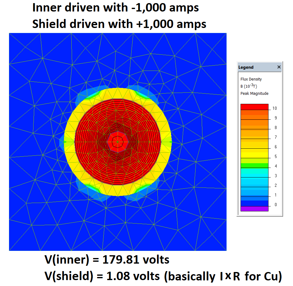
Because of the absence of flux loops from the outer conductor in its interior, the self-inductance of the outer conductor exactly equals the mutual inductance between the two conductors.
This seems incontestable.
The paper goes on to explain
What this means is that no longitudinal voltage will exist on the outer conductor due to inductance, if the inner and outer conductor currents are equal and opposite!
Which also seems incontestable. If the currents in the inner and outer conductors are equal and opposite, and the self-inductance of the outer conductor or shield is equal to the mutual inductance between the inner and outer conductors, then the total voltage magnetically induced by the inner and outer conductor currents on the outer conductor will be zero.
Consequently,
there will be no voltage difference between the source and load ends of the outer conductor due to inductance.
[However, there could be a voltage difference between the source and load ends of the outer conductor due to resistive voltage drop.]
Now let's consider the case where the coaxial cable is wired up "incorrectly", that is, with the center conductor grounded, and with an AC signal applied to the outer conductor.
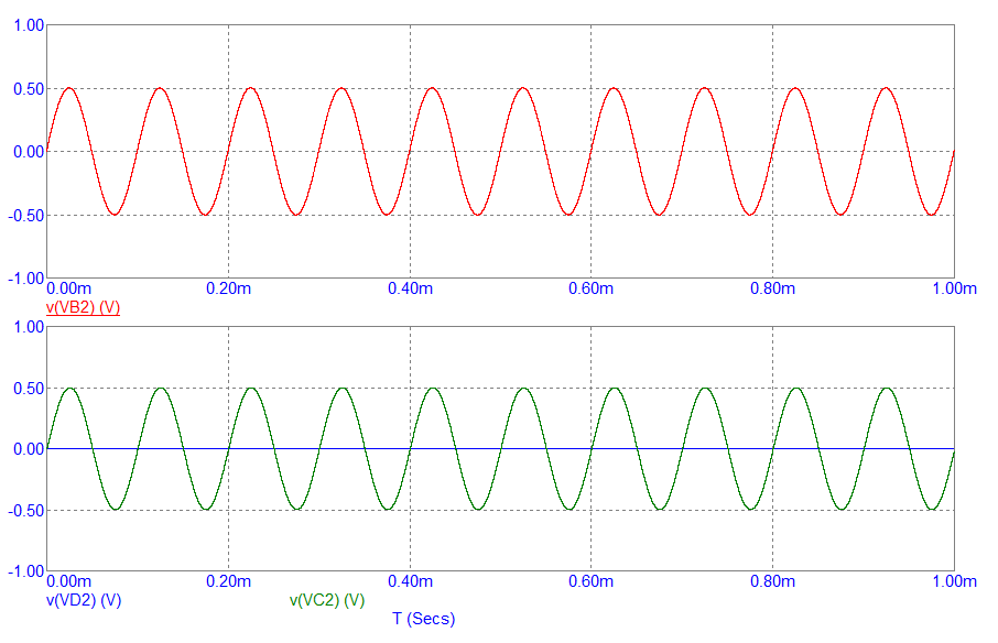
When a coaxial cable has particular lengths related to the frequency of a signal, the voltages at either end may be in phase due to some multiple of 2\$pi\$ phase shift occurring along the length of the cable. Let us assume that is not the case.
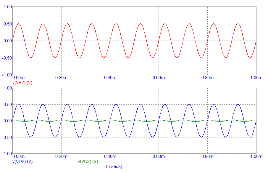
If we discount the possibility that the voltage at B is in phase with the voltage at D, and we discount the possibility that the voltages at B and D are constant, we seem to be left with the choice that the voltages of B and D are out of phase.
According to the analysis above, if the currents in the inner and outer conductors are equal and opposite, then there will be only a negligible resistive voltage drop across the outer conductor. However, since the voltages at B and D are out of phase, there must be a non-negligible voltage difference between them.
However, if there is a non-negligible voltage difference between B and D, this apparently leaves us with the conclusion that the currents in the inner and outer conductors cannot be equal opposite.
My questions
- Is this reasoning correct?
- If this reasoning is correct, how can one explain the different currents in the two conductors?
- If this reasoning is incorrect, where does it go wrong?
Odds and Ends
This question arose for me as I am working to understand this EESE answer.
Edit:
At this point, I believe that the reasoning is in error, and the source of the error lies in discounting the possibility that the voltage at B is in phase with the voltage at D. Another possibility, and the one that I believe happens in reality, is that the phase velocity of the voltage along the shield is infinite. At first my thoughts revolted against such an idea. How can fluctuations in the voltage at B instantly propagate to D?
However, upon reflection, I think this initial rejection of the idea that there is infinite phase velocity for the voltage between B and D is in error. My error lay in conflating the phase velocity of the voltage on the outer conductor relative to ground, with the phase velocity of the voltage on the outer conductor relative to the inner conductor. They are not the same. The phase velocity of the voltage relative to ground can be infinite because what we choose to call "ground" is arbitrary. The phase difference between an arbitrary point and ground does not need to "propagate". So whether or not the voltage on the outer conductor relative to ground is "fluctuating" is relative to our choice of what to call "ground". Once I accept that it is OK for the phase velocity of the voltage on the outer conductor (relative to ground) can be infinite, then I can accept that the voltage drop between the ends of the outer conductor is negligible. Once I accept that, I am no longer logically obliged to reject the fact that the currents in the inner and outer conductors are equal and opposite. All becomes right in the world.


Now let's consider the case....paragraph and, under the 2nd diagram you say....the two voltages will be out of phase- I don't know what voltages you refer to. You should be clear about this. \$\endgroup\$The current in the two conductors cannot be equal / in phase, because there is a voltage difference between the two ends of the outer conductor- I really don't see how you got to that statement fromAssuming the correctness of the notion that if the current in both conductors is equal then there will be negligible voltage drop across the outer conductor, we seem obliged to conclude that- so, maybe you should add an in between step that demonstrates your apparent result conclusion. \$\endgroup\$Odds and Endscan you be clearer about what you don't understand in my previous answer. Personally, I see your this new question as unrelated to the previous Q&A and so, if nobody managed to make an answer here then, where does that leave the earlier posting? This is problematic because, someone leaving an answer to an earlier question may not have available a time machine to jump into the future to understand your concerns BUT, say I did have a time machine, and read this question, I would still be left scratching my head about the "reasons" because, they are not explained. \$\endgroup\$