2
\$\begingroup\$

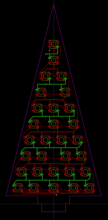
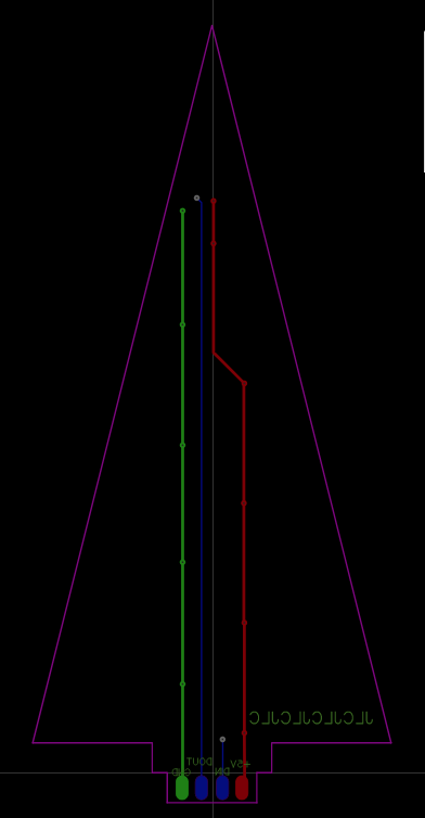
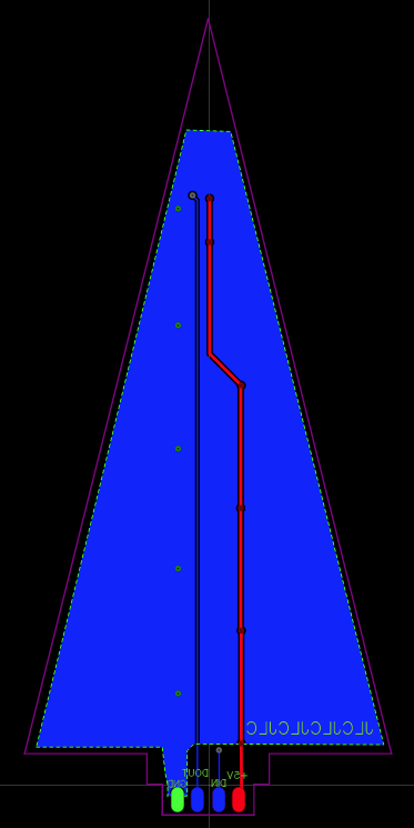
It's my first time designing a PCB. I had the idea to make a pyramid out of (probably) 6 same PCBs. Each pyramid would have 30 WS2812B B LEDs. Online I read that on the one side you should be concerned about the heat dissipation of the LEDs and on the other that those LEDs might not get that hot. Would such GND-Baseplate as in Back2 even serve any benefit?

I am also a bit confused about the width of the traces and power cables connected to the boards. I probably will power the boards in parallel (only the data in series) so the each cable wouldn't need to be that big but I still would need a good power supply. I have currently no idea about that. The GND and 5 V traces are currently 0.5 mm thick.

Can you give me some advice about the trace/cable sizes and the board design?

Top SIdeTop Back 1Back1 Back 2Back2

\$\endgroup\$
0

3 Answers 3

3
\$\begingroup\$

Third row from the bottom - adjust the spacing of the center two LEDs such that all 4 LEDs in that row are evenly spaced. The way you have them placed now, the gap in the middle will be huge when the board is lit.

Now, about the power --

0.5 mm is way to small for a power trace. You don't say what the maximum current per board is, but in this case there is another answer.

You are paying for all of the copper on all of the surfaces, so use it. On the component side, make the power and GND traces as fat as you can. Start at 2 mm and go up if you can. Remember, those traces also move heat. On the back side, split the board vertically into two poured planes. The blue signal trace can run right down the middle separating the two power planes, or be moved to the front side of the board, routed near an outside edge.

Connect the planes with the traces with many vias. Basically, the circumference of a via is the trace width of a very short connecting trace. Don't let this be a bottleneck for the current. If the thing at the bottom of the board is a connector with through-hole pins, make the via diameter the same as the pin holes. That is not a rule or requirement of any kind, just a way to reduce costs back when board houses charged extra for multiple hole sizes. Yes, I'm that old.

\$\endgroup\$
2
  • \$\begingroup\$ Thanks for the info. I didn't shar any max current because all i know atm is that the LEDs potentialy can draw up to 60mA each. So that would be 30*60mA = 1.8A per Board. (10,8A Total). Means i would need an 5v Supply which could push this amount right? That seems alot. What kind of cable would be needed to be run to each board than? \$\endgroup\$
    – fenryhord
    Commented Dec 15, 2021 at 15:13
  • \$\begingroup\$ For 2 A, I would go with #22 at a minimum, and #18 if possible. \$\endgroup\$
    – AnalogKid
    Commented Dec 15, 2021 at 18:14
1
\$\begingroup\$

It's a good idea to inject the supply voltage in regular intervals (as you did). For a first prototype I've connected these LEDs in series and noticed the voltage drop as a shift in colors.

At max brightness each LED draws about 60mA. So for each triangle you'll need to provide 30 x 60mA = 1.8A.

0.5mm power lines seems on the low end. The trace width depends on various factors like copper thickness. Here is an online calculator: https://www.7pcb.com/trace-width-calculator.php

These LEDs don't get too hot, but I'd recommend a ground plane. If it were my design, I would add a power and a ground plane (or a single mixed ground/power plane) for heat dissipation and good power distribution.

As Tony Stewart EE75 stated, 0.1uF caps are missing. Alternatively you can use the improved WS2813C LEDs, which don't need any extra components. They're only slightly more expensive.

As for the power supply, you need at least 6x 1.8A = 10.8A. Wire size table: https://www.powerstream.com/Wire_Size.htm

  • 12A: AWG11 (2.3mm)
  • 2.3A: AWG18 (1.02mm)
\$\endgroup\$
2
  • \$\begingroup\$ Thanks. I thought the LEDs i would be using would'nt need those extra capacitors as i read in the Datasheet (datasheet.lcsc.com/lcsc/…). Also would it maybe be better to use a 12V powersupply and us esomething like DC-DC Buck converters? And if so how would i need to size the 12v supply amperage wise? \$\endgroup\$
    – fenryhord
    Commented Dec 15, 2021 at 16:49
  • \$\begingroup\$ For my prototype I added the caps like the datasheet I found specified. Also, the LED stripes you can find on the market also include them. The power supply was something like this: de.aliexpress.com/item/… (5V/20A). And for the redesign I used a MAX17634CATP+ to convert 24V to 5V. \$\endgroup\$
    – Velvet
    Commented Dec 15, 2021 at 22:09
0
\$\begingroup\$

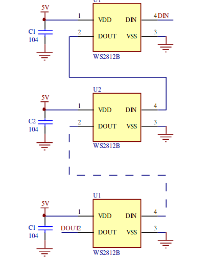
if you recheck your traces, you may find shorts across LEDs in the schematic. You ought to be able to do this on 1 side. Show schematic and check. Put all your LED's in the same orientation perhaps vertically and try diagonal traces to resemble branches. Each IC needs a cap too. 0.1uF. (104) but version control of specs leave, a lot to be desired for date code, reason for change with no Rev B. change, which may cause interference on data integrity. (Notoriously bad specs for signal integrity specs on traces, heat spreading and logic level noise)

enter image description here http://cdn.sparkfun.com/datasheets/BreakoutBoards/WS2812B.pdf

\$\endgroup\$
1
  • \$\begingroup\$ The Schematic would be just LEDs in series. Like this: imgur.com/KagzA7H I dont quite understand what you mean with branches. Isn't that what i have done with the vertical lines. Also i was going to use those "datasheet.lcsc.com/lcsc/…" which seem to dont need the caps. \$\endgroup\$
    – fenryhord
    Commented Dec 15, 2021 at 14:26

Your Answer

By clicking “Post Your Answer”, you agree to our terms of service and acknowledge you have read our privacy policy.

Not the answer you're looking for? Browse other questions tagged or ask your own question.