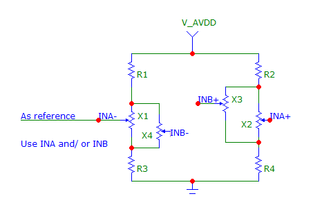
Sorry, but adding any components to the schematics is fighting a problem that does not exist.
Not to mention introducing additional components with their own thermal characteristics, on top of thermal drifts in the chip and load cells. This can only be justified if you add very complex schematics with thermistor, carefully calibrated for compensation.
HX711 already provides you with differential output, the only problem is that the combination of the chip with load cell has quite huge offset.
So, all you have to do is take a reading in the neutral position and then subtract it every time you read later. Or better yet, take several readings and calculate an average, for better precision.
When you do this all positive values would mean pressure applied in one direction, all negative values would be for other direction.
However keep in mind that many load cells will not return exactly to the center position when pressure removed. The usual way to deal with this is to have "dead zone" in your software, where any input is treated as zero.
UPDATE
Here is some primitive code I've used before to read two load cells with one chip. All you have to do is call Update() function often enough to keep reading data. You don't need any additional components for second load cell. Connect it as shown in the datasheet only use INB+, INB- inputs, there should not be much cross-talk between the channels.
#define GAIN_A_128  1   // Gain 128 (channel A) +/- 20mV @5V
#define GAIN_B_32   2   // Gain 32 (channel B) +/- 80mV @5V
#define GAIN_A_64   3   // Gain 64 (channel A) +/- 40mV @5V

int32_t value_a = 0;
int32_t value_b = 0;
bool current_ch = false;    // channel a = true, channel b = false

int ReadAndSetGain(int gain)
{
    // read chip data
    int ret = 0;
    // pulse clock pin 24 times to read the data as 2's complement value
    for (int i = 0; i < 24; i++)
    {
        gpio_set(clk_out_pin, true);
        gpio_set(clk_out_pin, false);
        ret = (ret << 1) + (gpio_get(data_in_pin) ? 1 : 0);
    }
    // set the channel and gain factor for next reading using clock pin
    for (int i = 0; i < gain; i++)
    {
        gpio_set(clk_out_pin, true);
        gpio_set(clk_out_pin, false);
    }
    // propagate sign bit
    if (ret & 0x800000) ret |= 0xFF000000;
    return ret;
}

// Call this function every 13 ms if HX711 data rate is 80 Hz,
// every 101 ms if data rate is 10 Hz to keep channel values updated.
// Note that default gain after reset is GAIN_A_128, so the channel values
// will be incorrect until after three successful readings.
void Update()
{
    // make sure data is available
    if (gpio_get(data_in_pin)) return;
    if (current_ch) {   // reading channel A
        value_a = ReadAndSetGain(GAIN_B_32);
    } else {            // reading channel B
        value_b = ReadAndSetGain(GAIN_A_64);
    }
    current_ch = !current_ch;
}
You can modify this code to suit your needs, of course. For example, instead of calling Update() periodically, you can read channels only when you need them:
int offset_a = 0;
int offset_b = 0;

int ReadA()
{
    while (current_ch) Update();    // make sure channel A has been read
    return value_a - offset_a;
}

int ReadB()
{
    while (!current_ch) Update();   // make sure channel B has been read
    return value_b - offset_b;
}

// call this in the beginning of a program when sensors are in neutral position
void Tare()
{
    // reset previous offsets
    offset_a = 0;
    offset_b = 0;
    // read and discard to initialize chip gain
    ReadB();
    // store current values as new offsets
    offset_a = ReadA();
    offset_b = ReadB();
}

