First post on here and not very experienced so let me know if there's anything wrong with my post as well as my design.
I am trying to layout a boost converter using the PAM2421AECADJR IC I bought as a prototype, but I'm having issues with the output dropping under any significant load.
Vin = 3.3 V, expected Vout = 12 V. I based the design on the recommended one in the datasheet
It seems to work fine with a 100 kΩ load, but drops to 6 V with a 10 kΩ load and quickly drops to ~3 V with anything below 10 kΩ.
Parts List:
- boost IC (PAM2421)
- 10uH Inductor (B78108E1103K000)
- Isat: 2A
- Fres,min: 20MHz
- Rdc: 136mΩ
- 470uF elec cap (KSY477M025S1A5H12K)
- Vmax: 25V
- ESR: 70mΩ
- Iripple: 1050mA/rms (105celcius, 100KHz)
- 10uF elec cap (MCGPR50V106M5X11)
- Vmax: 50V
- ESR: 16.579Ω
- Iripple: 70mA/rms (85celcius, 120Hz)
- 2.2nF (2200pF) ceramic cap (MCCC1KV222MZ5U)
- Vmax: 1KV
- 1uF tantalum cap (MCTAR25V105KA)
- Vmax: 25V
- 22pF ceramic cap (used as 2*22pF (parallel) = 44pF) (MCCC1500V220JNPO)
- Vmax: 1.5KV
- 0.01uF (10nF) ceramic cap (MCCC100V103KY5P)
- Vmax: 100V
- Schottky diode (SR1100)
- If: 1A
This is the prototype layout:
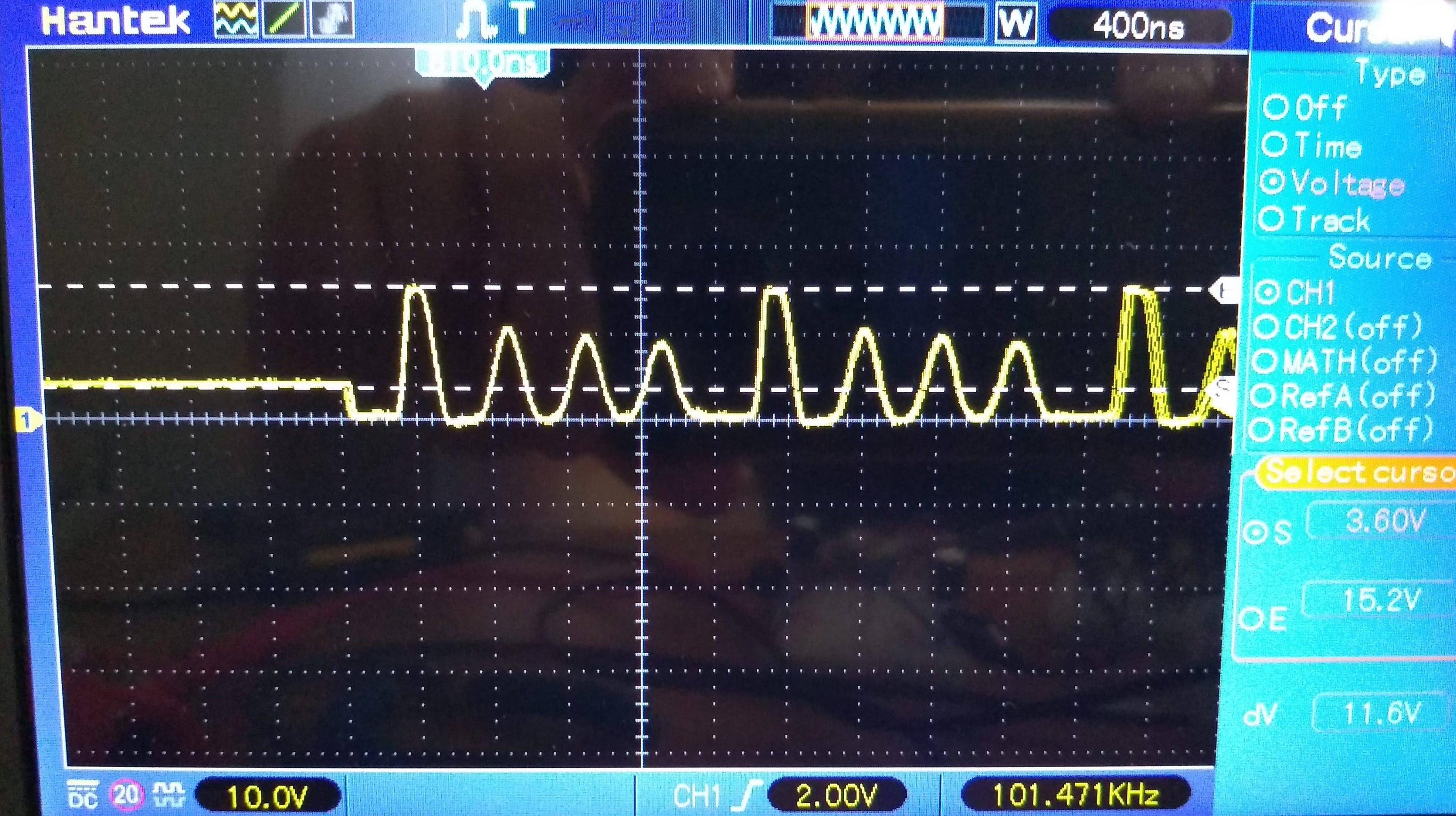
And this is the switching node voltage with a 100 kΩ load:
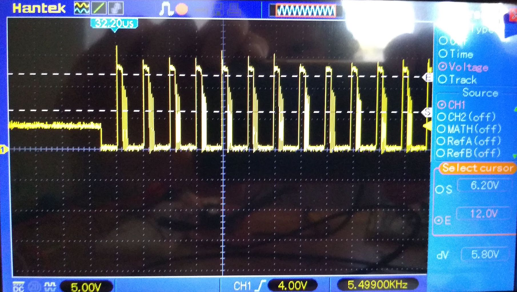
And with a 100 Ω load:
The inductor is one of the B78108E1103K000s which on paper seems like it should be good enough for this circuit (saturation current 2 A, 136 mΩ DCR).
I've tried to follow as much advice as I could find in terms of layout.
- switch loop as small as possible
- separate the PGND and AGND as much as possible (but connect at a single point)
Not sure what to do from here to get it to work, so hopefully someone can give me some suggestions.
Just for clarification, in the reference schematic, the inductor is 6.8uH (not 68), it's a little hard to see. And the actual value used in the breadboard is 10uH (as that's the closest I had)
UPDATE
I managed to get the circuit working, no change to the schematic or components used, just by swapping to a protoboard and putting a massive blob of solder and bare wire together to make a large ground plane. After doing that, the output voltage was stable with both the 100 kΩ and 100 Ω loads as well as a 12V audio amplifier with good results


