1
\$\begingroup\$

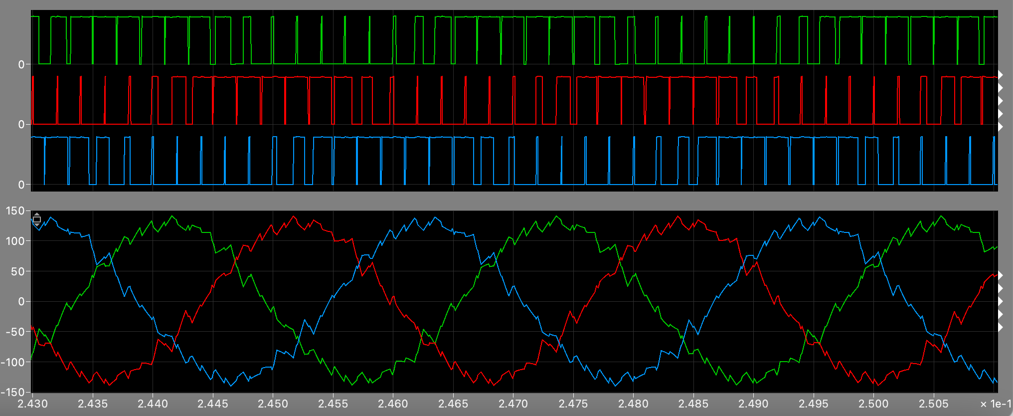
I have made a simple three-phase inverter in Simulink. I have the output waveforms for the line-voltage and current as shown below, where the voltage is in plot 1 (I have split the waveforms for clarity) and the current is in plot 2:

enter image description here

This is as I expected; however, how would I calculate the output power?

Would it be correct to find the RMS for the voltage and multiply with the current because otherwise the power out will turn on and off as the voltage does? I can't seem to understand it myself so any help is very appreciated

\$\endgroup\$
2
  • 1
    \$\begingroup\$ No, the graphs make no sense to me. It looks like your current is a square wave. What is needed is clarity. It may make sense to you but it's not you who is reading this post. picture 1a appears to be irrelevant. Picture 1b appears to be voltage. Picture 2a and 2b make no sense. A picture that shows 3 phase voltage that is time-aligned with a picture of 3 phase current is required. Show at least two full cycles and no more than 3 full cycles. \$\endgroup\$
    – Andy aka
    Commented Jan 13, 2022 at 12:34
  • \$\begingroup\$ Thanks Andy- for your information the square wave is the voltage- the high switching frequency means that in order to see the voltage waveform clearly I have zoomed in on 1a and 1b to show 2a and 2b. I will redo the waveforms with lower switching frequency so it can be seen more clearly in one set of plots. \$\endgroup\$ Commented Jan 13, 2022 at 12:39

1 Answer 1

3
\$\begingroup\$

Would it be correct to find the RMS for the voltage and multiply with the current because otherwise the power out will turn on and off as the voltage does?

No that would not be correct. Look at this extract from your waveforms: -
enter image description here

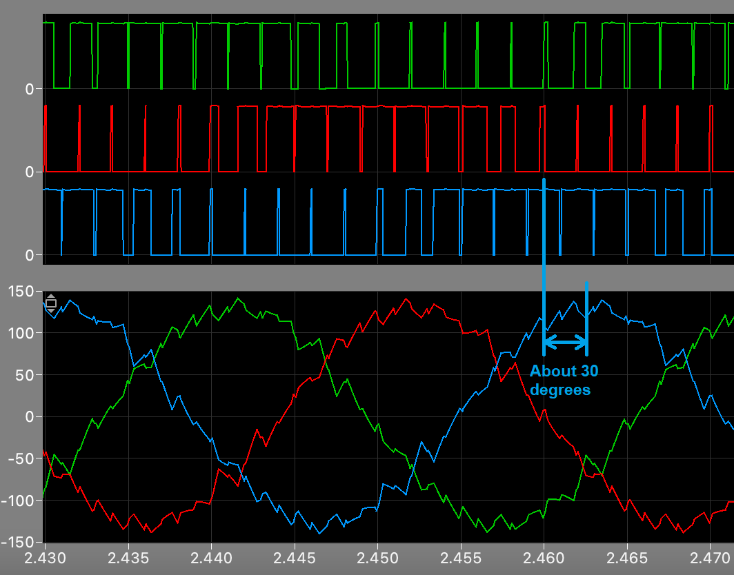
I've focussed on the middle/maximum point of the blue voltage waveform and, I've looked at the phase difference between it (if it were a sinewave) and the current waveform. There is a 30° phase shift. That's not surprising if you have a 3 phase wye connected load; comparing line voltage and phase current for a resistive wye load always produces a 30° phase shift like this.

So, if you calculated \$V_{RMS} \times I_{RMS}\$ you would get an error.

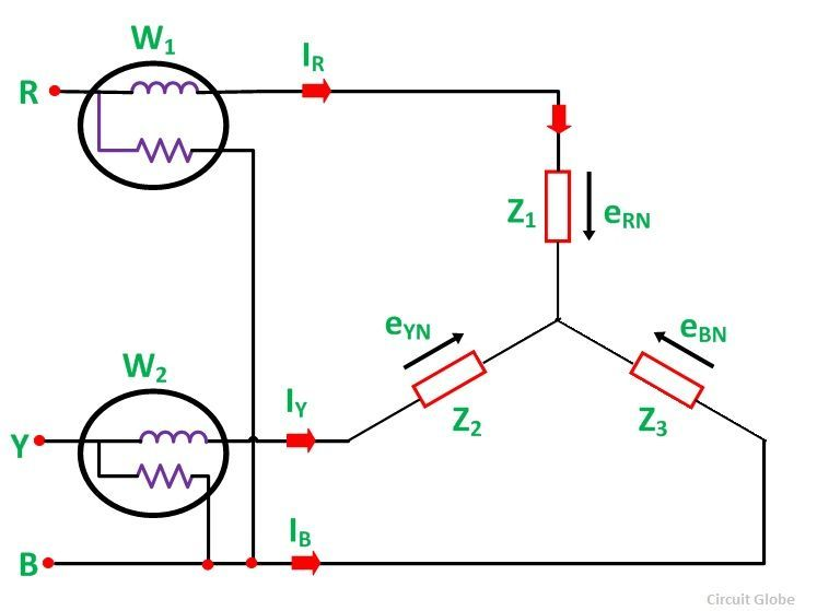
The only way to find the power is by emulating the two-wattmeter method: -
enter image description here

Image from here. It measures true power put into a load on a 3 phase system.

To emulate it you need to calculate power twice (a la 2 wattmeter method). Power can be calculated by taking instantaneous values of the voltage waveform and multiplying each by the instantaneous value of the current waveform. Then average the resulting power waveform to obtain power. You need to respect that fact that the sampling of each waveform needs to be done at a rate that is several times faster than your 3 phase fundamental frequency and, given that the voltage waveform is basically rectangular in nature, it's probably sensible to go for something like 100 samples per cycle if not more).

Repeat for the "other" wattmeter and add the two powers to get true power consumed by the load. Of course, if this is just a simulation then it's a lot easier.

\$\endgroup\$

Your Answer

By clicking “Post Your Answer”, you agree to our terms of service and acknowledge you have read our privacy policy.

Not the answer you're looking for? Browse other questions tagged or ask your own question.