4
\$\begingroup\$

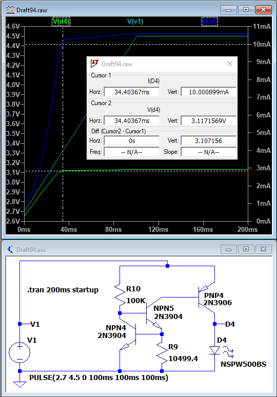
I built the circuit suggested by @MicroservicesOnDDD in their answer to this question: Low Overhead Constant Current LED Driver and had a play. Here's the circuit in the linked question:

enter image description here

The most LED current I could get by adjusting R9 was 100mA. I've got a 1W power LED (forward voltage around 3.2V) and so I want to get the current up to around 325mA whilst minimising losses.

I'm driving it from either a lithium ion 3.7V battery (maximum 4.2V at full charge) or 3 NiMH in series (maximum 4.5V at full charge.)

Any suggestions on modifying the circuit?

I've tried to add another PNP so it forms a Darlington pair with the existing PNP transistor and keeping the LED at the joined collectors but am not making progress.

\$\endgroup\$
3
  • 1
    \$\begingroup\$ You can't minimize losses with a linear circuit. Linear circuits work by burning off excess voltage from the supply as heat. Losses remain unchanged for a given input and output. So you should forget about that objective if you want to keep using this style of circuit. \$\endgroup\$
    – DKNguyen
    Commented Jan 25, 2022 at 15:18
  • \$\begingroup\$ There are many circuits 'out there' to acheive this that are very inefficient, having lots of components each consuming power. Those are the losses I'm trying to minimise. \$\endgroup\$ Commented Jan 25, 2022 at 15:56
  • \$\begingroup\$ @MarkHightonRidley If staying simple and linear, I'd pair up a BJT (for measuring the current) and a FET (for controlling the current.) About 700 mV minimum total overhead. So it may work down to 4 V. No opamp needed. \$\endgroup\$
    – jonk
    Commented Jan 26, 2022 at 7:31

2 Answers 2

6
\$\begingroup\$

Your circuit will not work at the end of the discharge cycle: there isn’t enough voltage to light the LED. This is regardless of whether you use a BJT or FET (although the FET will be sightly better having only Rds(on) vs. Vce(sat)) or sense using an op-amp.

Even then, op-amp selection is slightly tricky: it needs to work at the low voltage, and permit inputs close to ground for low-side sensing. A low-voltage version LMV321A could work.

But, this still doesn’t fix things as the battery falls below 3.2V: your LED will get dim.

Instead, consider a buck-boost converter. This extends the voltage range and gets good efficiency. Here’s one that uses a charge pump: http://www.sg-micro.com/uploads/soft/20190626/1561535688.pdf

Another source: https://assets.maxlinear.com/web/documents/sipex/datasheets/sp6686.pdf

\$\endgroup\$
6
  • \$\begingroup\$ Thanks for that point, @hacktastical. My design choice is that I'm happy for the LED brighteness to fall off a lot as the battery voltage drops to below around 3.5V as both types of batteries will have delivered most of their capacity by then. \$\endgroup\$ Commented Jan 25, 2022 at 15:43
  • \$\begingroup\$ Li-ion will have only delivered 50% of its mAh capacity. It can be safely drawn down to 3.0V. See: batteryuniversity.com/article/… The story is similar for NiMH. \$\endgroup\$ Commented Jan 25, 2022 at 15:53
  • \$\begingroup\$ I stand corrected, thanks @hacktastical! I've been learning so much in recent weeks, not all of it has stuck correctly ;) \$\endgroup\$ Commented Jan 25, 2022 at 15:59
  • 1
    \$\begingroup\$ The buck-boost devices shown use a 33 mOhm sense, and 50~150mV feedback voltage. They sense current, not voltage. \$\endgroup\$ Commented Jan 25, 2022 at 16:29
  • \$\begingroup\$ I found the LMV321A is only available in packages I can't work with @hacktastical - I'm building on a stripboard. I've done lots of hunting and found the LM4562NA/NOPB, datasheet here: ti.com/lit/ds/symlink/lm4562.pdf It's rail-to-rail and seems to be a good alternative. Do you mind having a look before I order some? Thanks! Mark \$\endgroup\$ Commented Jan 26, 2022 at 13:01
4
\$\begingroup\$

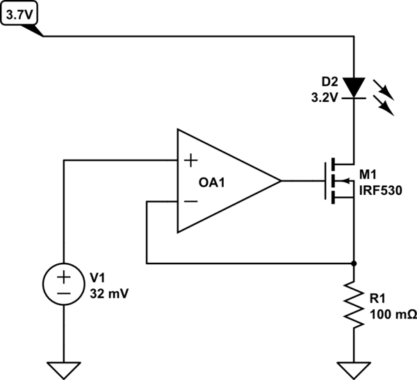
TL,DR: Opamp that controls a MOSFET

If you have low headroom voltage, that means you cannot use a large resistor to sense the current and provide feedback.

Instead you use a small resistor like 100 mOhm. That will drop only 32 mV at 320 mA. Use an op-amp to regulate the voltage drop across this sense resistor to be 32 mV.

schematic

simulate this circuit – Schematic created using CircuitLab

You can realise the 32 mV reference with a resistance divider depending on your accuracy needs. Use an opamp that contains the low supply in its common-mode input voltage range.

\$\endgroup\$
4
  • \$\begingroup\$ Thanks, @tobalt, itlooks like it will do as I want. I'll get hold of an appropriate op amp as suggested and give it a try. I still would like to know how to adjust the original circuit for my own learning :) \$\endgroup\$ Commented Jan 25, 2022 at 15:29
  • 2
    \$\begingroup\$ @MarkHightonRidley also use a MOSFET with low enough turn on voltage. so that you can turn it on with the available output swing of the opamp. Basically just use a rail-to-rail input-output opamp and MOSFET with maximum of around 2.5V gate threshold voltage. As you have spice, you can check how different MOSFET will cope. \$\endgroup\$
    – tobalt
    Commented Jan 25, 2022 at 15:32
  • 1
    \$\begingroup\$ Thanks for your guidance @tobalt and hacktastical. I've now got a properly working circuit. I used a MCP6021 PDIP package op amp (perfect for stripboards) and an IRLB8721 MOSFET. For the reference voltage I used a resistor divider (150kΩ and 1.2kΩ). \$\endgroup\$ Commented Feb 2, 2022 at 9:45
  • 1
    \$\begingroup\$ @MarkHightonRidley Thanks for reporting back! I wish many more people did that :) Usually, people only return if things don't work out as planned. \$\endgroup\$
    – tobalt
    Commented Feb 2, 2022 at 10:30

Your Answer

By clicking “Post Your Answer”, you agree to our terms of service and acknowledge you have read our privacy policy.

Not the answer you're looking for? Browse other questions tagged or ask your own question.