15
\$\begingroup\$

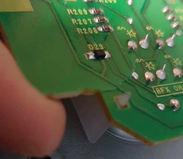
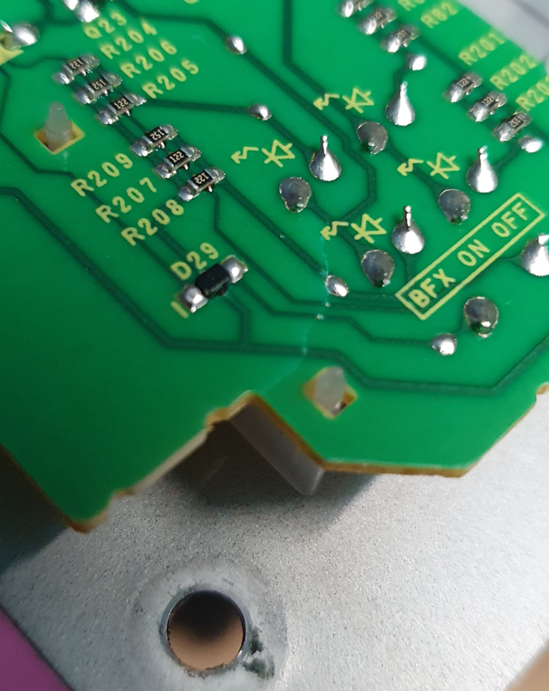
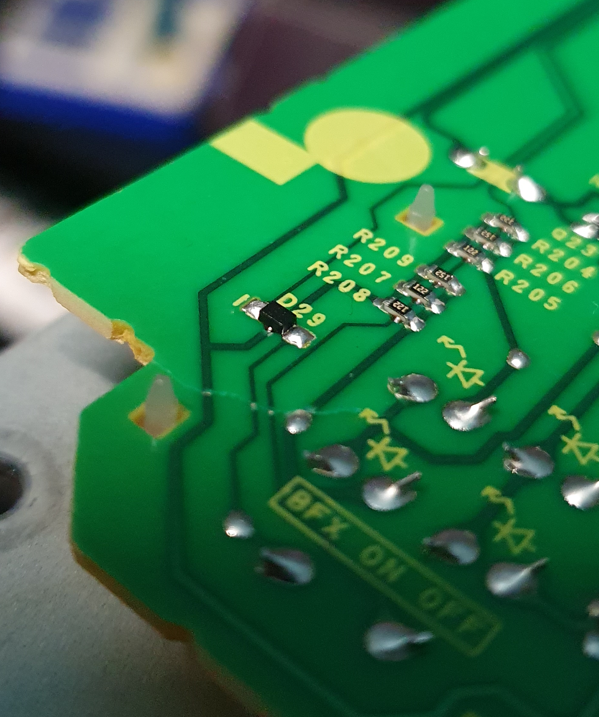
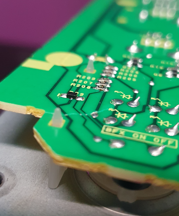
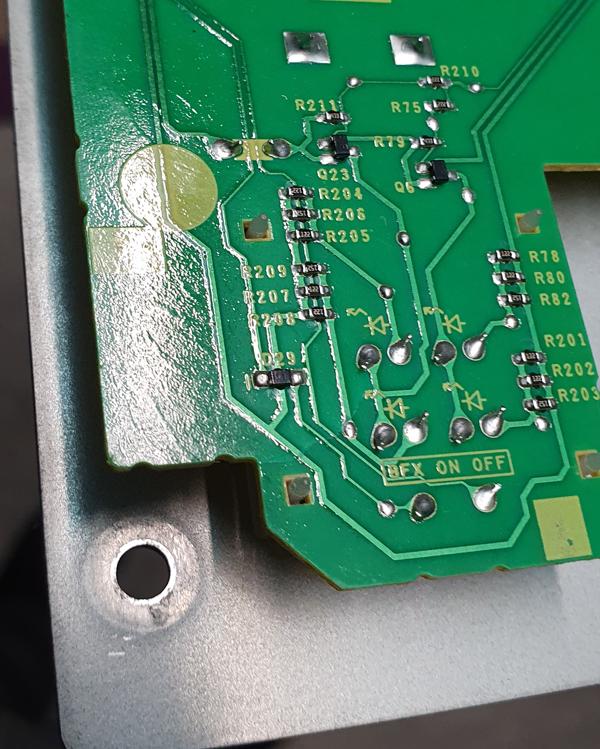
When replacing a component on my DJM450 (DJ Mixer) I stupidly cracked a small part of the PCB. Now, in terms of effect for me, it's minimal but very annoying.

I want to repair it, if possible.

enter image description here enter image description here enter image description here enter image description here enter image description here

Every video, walkthrough, etc I have seen has not addressed the PCB as I understand it in these photos.

So, does anyone have a guide or advice? Is it worth attempting the repair considering that I have a workaround if I have to?

Most of the videos I have seen have done the work between the "lines". Where as, if I am correct, I would need to repair/ solder the actual copper "lines". Am I mistaken?

--

Edit: For clarity before I close;

  • It's a DJM-450
  • It's only got design/ "lines" on one side of the board (the side you can see)

What I did;

  • Scraped back the coating on the board
  • Soldered the "lines" using small solder (clamped the board and had someone hold a light for me!)
  • Did a quick test to ensure it was working
  • Using epoxy on the other side, sealed the board
  • Tested working again and screwed back in place.

Thank you all.

\$\endgroup\$

4 Answers 4

29
\$\begingroup\$

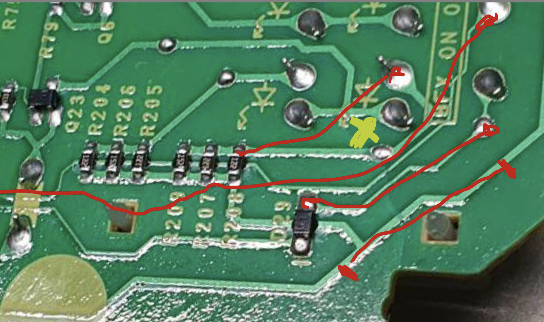
Look at the copper traces on each side of the board. Find a solder pad that each of the (on each side of the crack) gives access to the trace. Solder some 24 to 28-gauge wires to those pads that essentially bridge across the crack. It looks like 4 traces are impacted on the side you show. There may be more on the other side. Based on the low quality design and lack of copper flood, I'm guessing it is a two layer board and you have no inner layers to worry about.

Also, drill a 1.5mm hole (1/16" hole) through the crack to stop crack propagation. Ideally at the end of the crack or within 10mm of the end of the crack if components are in the way. See yellow x. Best loactation I can see but you'll have to check other side of the board for any interferences.

enter image description here

\$\endgroup\$
4
  • 3
    \$\begingroup\$ Manually drill with a drill in a pin vise. Just twist back and forth. Or if you have strong fingers no need for a pin vise. Your local radio control model (like cars and airplanes) store might also have a drill with a knob on it for a couple of bucks. Used to drill servo horns. Because the crack is there, you want to clamp it directly opposite of the crack if possible and directly support the back opposite of the drill. Power drill will just destroy things, especially with the crack there. \$\endgroup\$
    – DKNguyen
    Commented Feb 5, 2022 at 18:52
  • \$\begingroup\$ While not the exact solution I went with, this is very helpful and good to know. I went with the scraping back of the "lines" and managed to very carefully solder them. However, if that did not work, this was the next step I would of taken, so simply because you gave me a viable option and alternative. Best answer, thank you! \$\endgroup\$
    – Kyle93
    Commented Feb 6, 2022 at 17:34
  • 1
    \$\begingroup\$ @Kyle93 Did you just use blobs of solder to reconnect the traces? You probably should have buried a small piece of solid strand wire under there to bridge the break. \$\endgroup\$
    – DKNguyen
    Commented Feb 6, 2022 at 18:20
  • \$\begingroup\$ @kyle93 you should look at te trace just above the yellow X in my drawing. That trace may be cracked as well. \$\endgroup\$ Commented Feb 6, 2022 at 23:04
11
\$\begingroup\$

If by "repair" you mean broken traces then if it's a 2-layer board, get a fiberglass burnishing pen and rub off the solder mask around the breaks in traces so you can solder to reconnect them.

If it's not two layer you are SOL.

If you mean the mechanical crack then glass fabric with with low viscosity composite epoxy resin away from the traces on both sides? But you are liable to functionally mess the board up if the resin runs the wrong way out of the fabric. And the glass might not adhere best to the solder mask which would mean you need to scrape it away in those areas too.

Or buy bare FR4 or G10 which is the same stuff the PCB is made of (glass/epoxy) and cut it into strips and epoxy it into place with regular epoxy away from the traces. You can cut 1/32"/0.8mm and thinner FR4 with scissors.

Splinting the board before repairing traces makes repairing traces easier but only if you don't mess up and get epoxy on the traces or too close to the traces (normal epoxy won't withstand soldering heat). Recommend a tiny clamp on the corner to hold the crack steady so you electrically repair the board first.

\$\endgroup\$
5
  • 3
    \$\begingroup\$ There is a really good chance this is a single-sided board. \$\endgroup\$ Commented Feb 5, 2022 at 19:15
  • 1
    \$\begingroup\$ That would certainly making splinting easier. Just make cutouts for the components on the splint and epoxy the whole damn thing down. \$\endgroup\$
    – DKNguyen
    Commented Feb 5, 2022 at 19:29
  • 2
    \$\begingroup\$ For reference, it was a single side board. I was able to resolder the points in the photo and then stick the whole things back in one bit. Thank you very much for the information, super helpful and made up a great part of what I did. \$\endgroup\$
    – Kyle93
    Commented Feb 6, 2022 at 17:35
  • \$\begingroup\$ Even a 4-layer board can be fixed this way by carefully scraping/peeling off the top layer near the crack, soldering the bottom traces and then soldering tiny bridges over the top layer traces. \$\endgroup\$
    – rustyx
    Commented Feb 7, 2022 at 10:40
  • 2
    \$\begingroup\$ From the images it seems the PCB is not FR4 or some other fiberglass stuff. It seems the phenolic type. This would also explain the crack looks. If it were FR4 it would be very hard to cause such a crack by accident. \$\endgroup\$ Commented Feb 7, 2022 at 14:30
7
\$\begingroup\$

If it's more than a 2-sided board then unless you have a layout of the internal traces, you're probably out of luck. You can try putting it back together and hope that all there is in the broken area is ground and power planes and that they're not shorted -- it depends on how much you love your mixer, and how much money and effort it'd take to replace it.

What GT Electronics said about drilling the end of the crack to stop it from propagating.

I would do the following:

Mechanically fix the board. I would do this by scuffing areas of the board that don't have traces, across the crack, and then epoxying some scrap pieces of PCB material across the crack. This, plus the crack-stop hole will prevent the board from breaking up worse. Use good epoxy; name brand in your area (good hobby/consumer-grade ones in the US are Devcon, Gorilla, or Bob Smith Industries; actual industrial-grade would be better).

Electrically fix the bad traces. My inclination would be to scrape the solder mask off of the traces around the crack and patch with wire with diameter about half the width of the trace. GT Electronics is probably right about using wires that start and end at component holes -- I'd probably still scrape the solder mask, and solder the wire down on top of the trace. It's probably not at all a concern on that board, but in the event that the traces have high frequency or noise-sensitive signals on them, following the original traces will get you as close as possible to the original designers intent.

Just for personal improvement, review what you did to break the board, and try not to do it again! I've learned innumerable lessons from innumerable mistakes, but only where I've done so purposely.

\$\endgroup\$
1
  • \$\begingroup\$ I know exactly what I did to break it and when I put the whole thing back in place, made sure to not repeat the same mistake! I say it in my day job (IT MSP) and that you can only learn by breaking things and finding out how to fix them. I've learnt something new here and I've learnt how to not make the same mistake again :) \$\endgroup\$
    – Kyle93
    Commented Feb 6, 2022 at 17:37
-1
\$\begingroup\$

Existuje elektovodive pero na opravy plošinych spojov masku (to zelené) z plochy môžeš oškrabať aj tenkým plochým skrutkovačom ale opatrne a potom podľa návodu na pere prepojiť poškodené plochy. Po uschnuti odporúčam prelakovať

In English: "There is an electrically conductive pen for repairing the joints mask (the green) from the surface you can scrape with a thin flat screwdriver but carefully and then follow the instructions on the pen to connect the damaged surfaces. After drying, I recommend repainting"

\$\endgroup\$
0

Your Answer

By clicking “Post Your Answer”, you agree to our terms of service and acknowledge you have read our privacy policy.

Not the answer you're looking for? Browse other questions tagged or ask your own question.