2
\$\begingroup\$

I'm using a homebrew encoder based on two A3144 hall sensors (logic, open collector) to control motor rotation. It's connected to the MCU via 2 metres of fancy double-shielded cable with 1K pull-up resistors and tends to work pretty well.

But now I need to connect to that same encoder from 20..30 m away from the MCU. Environment is quite noisy, so I want to use RS-485 ICs and twisted pairs for that task. The RS-485 will just carry encoder pulses, not some data.

The only downside of this solution that I can think of is power dissipation. Depending on the rotor position, an RS-485 line can stay high for minutes, running current through the termination resistor.

I think that RC termination should do the trick, but I'm not sure how to calculate the capacitor value. The pulse frequency is 75..300 Hz, so extremely low compared to normal RS-485 operation. Maybe there is some solution suitable for my case that is not recommended for RS-485 networks.

I know that there are some industrial encoder protocols based on RS-485, but they look over-complicated for this task.

\$\endgroup\$
2
  • \$\begingroup\$ ti.com/lit/an/slla272d/slla272d.pdf?ts=1644299362814 \$\endgroup\$
    – schnedan
    Commented Feb 8, 2022 at 12:05
  • \$\begingroup\$ A very warm welcome to the site. Please can you edit your question and greatly improve it, splitting up the single slab of text into paragraphs and using full stops instead of commas that make really long sentences. The better the quality of your question, the better the quality of the answers it will attract. Again, welcome. \$\endgroup\$
    – TonyM
    Commented Feb 8, 2022 at 12:28

4 Answers 4

2
\$\begingroup\$

RS-485 runs current through the termination resistor in both states; only the direction of the current changes. So AC termination indeed can be used to save power.

National SemiconductorTI's application note AN-903 A Comparison of Differential Termination Techniques describes how to size the termination capacitor:

  CT ≤ (cable round trip delay) / Z0 ≈ (2 × 20 m × 5.5 ns/m) / 120 Ω ≈ 1.8 nF

And the RC time constant should be less than 10 % of the length of a bit.

\$\endgroup\$
2
\$\begingroup\$

If this is point to point (as opposed to a multidrop topology), you will be fine with series source termination resistors at the driver end, and leaving off the parallel termination at the destination. This approach is very beneficial if power draw is a consideration.

A good starting value for the source termination resistor is 33 ohms. The "best" value depends on the Zo of your cable and the output impedance of the '485 driver. This is where a simulation tool can help. But you need to make sure you use the right models for the cable and driver.

\$\endgroup\$
1
\$\begingroup\$

If someones life or money is not dependent on your motor, then you can don`t bother about shielding, termination or pull-ups/pull-downs on A-B circuit in slow speed/short cables. Just use twisted pair.

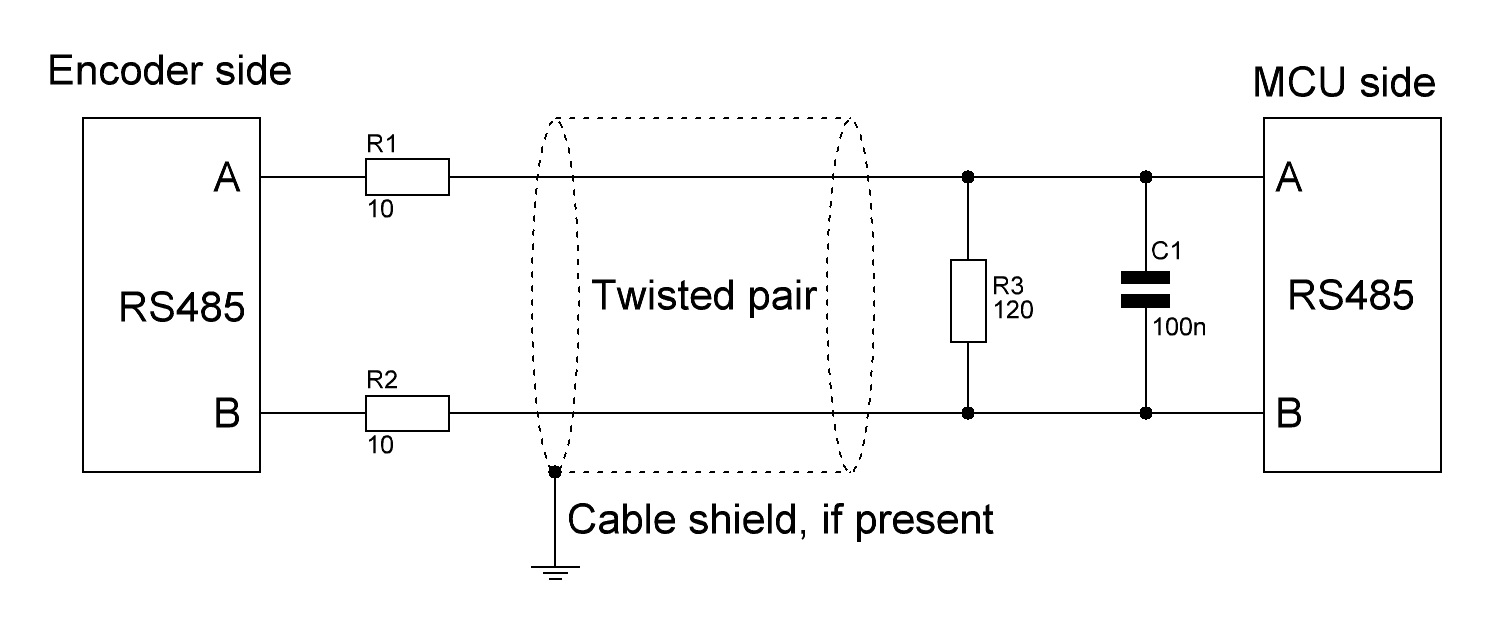
I`m suggesting scheme below, if you want some protection.

enter image description here

I presume that dataflow is unidirectional from encoder to MCU.

R3 - resistance value depends on cable impedance (look for its datasheet). If you dont know impedance - take 120Ohms.

R1,R2 - resistance value calculated from R3 max power and 12V (rs485 A-B lines worst case voltage). Also they will reduce RS485 driver current consumption in case of short circuit A-B line.

C1 - reduce some noise (RC filter with resistors). Its value depends on minimum impulse time (both high and low levels) of your system.

Rough estimation:

  1. Determine minimum impulse time value. Divide it by 10.
  2. Select resistors and capacitor values from formula Cmax = Tmin / Rtotal.

Good online caculator for filters: http://sim.okawa-denshi.jp/en/Fkeisan.htm

Pull-ups and pull-downs for TX/RX lines of rs-485 IC you can find in your ICs datasheet. Or look for any Texas Instruments RS485 IC - they often have examples.

\$\endgroup\$
0
\$\begingroup\$

Not sure why you got downvoted, but I actually think this is a nice idea.

The only downside of this solution that I can think of is power dissipation, depending on rotor position rs485 line can stay high for minutes running current through the termination resistor

Regular RS485 chips should have no problem with that. From TI,

an RS-485 transceiver’s driver must be able to drive 1.5V across 32 unit loads and two 120Ω terminations

Also, you'd most likely be fine even without any termination resistors at that speed, though it's always nice to have one.

\$\endgroup\$

Your Answer

By clicking “Post Your Answer”, you agree to our terms of service and acknowledge you have read our privacy policy.

Not the answer you're looking for? Browse other questions tagged or ask your own question.