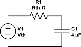
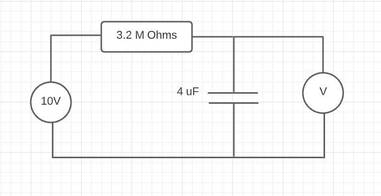
If the voltmeter's internal resistance is comparable to the 3.2 MOhm, then the loading effect is important and worth considering. We can form a Thévenin equivalent for the circuit attached to the capacitor (i.e. the voltage source, its series impedance, and the loading impedance of the voltmeter):

simulate this circuit – Schematic created using CircuitLab
where Vth and Rth are a consequence of both resistances. We can show that:
$$R_{th} = \left(\frac{1}{3.2\,[\text{M}\Omega]} + \frac{1}{R_{\text{voltmeter}}}\right)^{-1} $$
and
$$V_{th} = \frac{R_{\text{voltmeter}}}{3.2\,[\text{M}\Omega] + R_{\text{voltmeter}}}$$
You might recognize the second equation as being a simple voltage divider. However, it's worth noting that the capacitor charges to a lower voltage, but its time constant is shorter since it sees a smaller effective impedance across its terminals.


