1
\$\begingroup\$

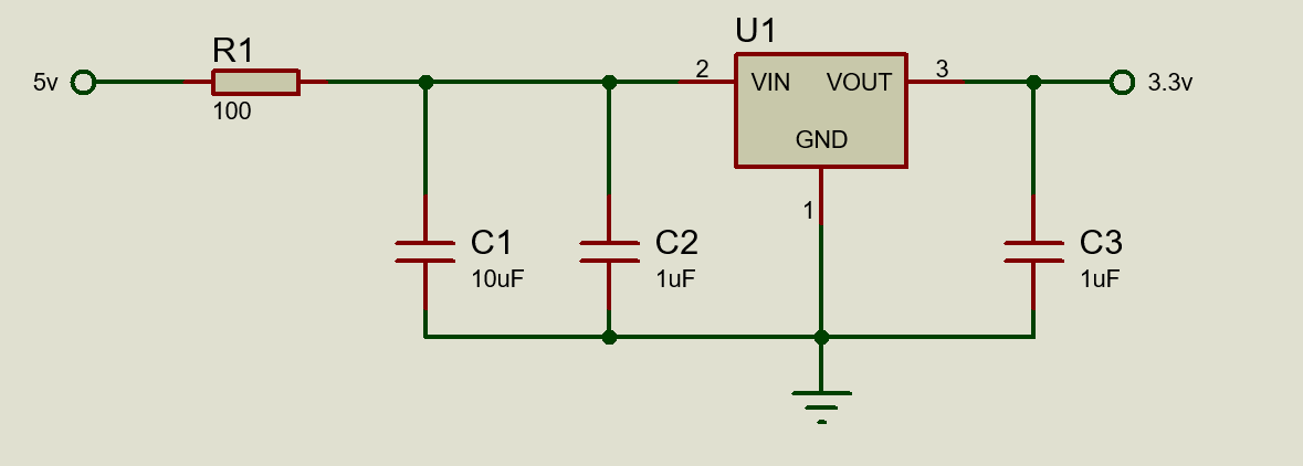
I would like to use an RC filter to filter out noise, since the down stream components only needs a maximum of 30mA.

Is it possible to use such a large resistor on the RC filter to achieve very low cut off frequency?

enter image description here

A 100 ohm - 10 uf combination will give me about 159 Hz cut-off which is pretty good. The LDO will be current limited to 50mA (5v/100ohms) which I don't mind since the circuit downstream is only 30mA.

Will the output of the LDO still be 3.3V? If not, how do calculate what the output voltage will be so I can adjust the resistor in order for me to have a 3.3V output?

\$\endgroup\$
9
  • 3
    \$\begingroup\$ 30 mA through 100 ohm = 3 V (dropped across R1). This won't work. \$\endgroup\$
    – Chu
    Commented Feb 13, 2022 at 11:10
  • 2
    \$\begingroup\$ You might find some regulators will go unstable so, choose carefully and read the data sheet. \$\endgroup\$
    – Andy aka
    Commented Feb 13, 2022 at 11:11
  • \$\begingroup\$ @Andyaka what should i typically look for in the datasheet that says i cant do it? a quick skim on the datasheet and i dont find anything that says i can place a series resistor on its input. \$\endgroup\$
    – DrakeJest
    Commented Feb 13, 2022 at 11:51
  • \$\begingroup\$ Link the data sheet. There may be no general statement but there might be clues. \$\endgroup\$
    – Andy aka
    Commented Feb 13, 2022 at 12:35
  • \$\begingroup\$ @Andyaka i have already linked the datasheet in my original post. I hyperlinked it to the word 'LDO' in the paragraph after the picture. The LDO is an LP5907 \$\endgroup\$
    – DrakeJest
    Commented Feb 13, 2022 at 13:48

2 Answers 2

2
\$\begingroup\$

Of course there can be a RC filter before the LDO.

But the reaistor value is wrong.

The LDO needs more than 3.3V at input to provide 3.3V output. The LDO says the dropout voltage is 250mV and otherwise the LDO parameters are measured at VIN = VOUT + 1V. The 250mV assumes that output has already dropped by some percentage when drawing a certain amount of current.

If you want to play safe, there must be 3.3V+1V = 4.3V at the LDO input while 30mA flows, so you can calculate the resistance required.

\$\endgroup\$
2
  • \$\begingroup\$ im only drawing 50mA which should give me a much lower dropout of the rated (100mA = 50mV drop) so wouldnt the max 250mV dropout enough for me? 1V seems to much of an overhead. For resistor calculation, ill use your 4.3v as a target. so for a 0.7v drop at the resistor i must use a 23 ohm resistor , correct? \$\endgroup\$
    – DrakeJest
    Commented Feb 13, 2022 at 11:48
  • 1
    \$\begingroup\$ You are right, you can use much lower dropout voltage as the current is much less. And your resistor calculation is correct. \$\endgroup\$
    – Justme
    Commented Feb 13, 2022 at 11:53
2
\$\begingroup\$

This LDO's datasheet specifies PSRR with a dropout voltage of 0.9V, which is pretty much normal.

At low dropout voltage, the PMOS pass transistor in the LDO gets its Vds squeezed. As with all other FETs, at low Vds its capacitance increases (ie, its bandwidth is reduced), and it loses transconductance. This means it requires more drive from the error amp, and it also gets harder to drive: to change its output current by a small amount \$ \delta i \$, both the required Vgs swing and the associated gate drive current increase. The pass MOSFET is part of the feedback loop, so this translates into a loss of open loop gain and bandwidth. PSRR, which depends on feedback, will thus decrease at low dropout voltage, sometimes quite dramatically.

At high enough dropout voltage, the FET behaves as a controlled current source: changes in Vds result in small changes in Id, so the intrinsic properties of the FET help with PSRR, which the feedback loop then improves. At low dropout, it behaves more like a controlled resistor, so it does pretty much nothing for PSRR which then only depends on feedback.

If your goal is to increase PSRR, using a very low dropout voltage would defeat the purpose.

I would leave 1V dropout on the LDO to get the pretty good PSRR specified in the datasheet, so at 30mA this corresponds to 0.7V dropped on the resistor, which means a resistor value of 22 ohms.

If you really want to increase PSRR at high frequency, then a ferrite bead in series with the resistor would be an option. At this low current, you can use a 300-600R ferrite, it probably won't saturate. Adding a few ohms (maybe 10 ohms) in series avoids LC resonance with the caps.

If you want to increase PSRR at low frequency, you'll have to use a larger capacitor, which will then be an electrolytic. You can use 470µF 6V3 FR from Panasonic for low ESR for example. However, you could also just put two LDOs in series, for example the 4.5V one then the 3V3 one.

Note high PSRR and low noise regulators are only meaningful for constant current loads. If the load draws variable current, then the output voltage variations can be dominated by that instead of PSRR.

\$\endgroup\$

Your Answer

By clicking “Post Your Answer”, you agree to our terms of service and acknowledge you have read our privacy policy.

Not the answer you're looking for? Browse other questions tagged or ask your own question.