0
\$\begingroup\$

I plan to use the ESP-12E's GPIO pin to dim a 12 V LED strip wire and control a 5 V [WS2812B] 1 panel via CAT 5.

I tried using a 10 ft CAT 5 cable to link the ESP12E pin to the DIN pin on the WS2812B panel, however, the LED panel did not change color.

When I tried to dim a 12 V LED by sending a signal to a MOSFET (IRFZ44N)via a 10 ft CAT 5 wire, the identical problem occurred. When I tried to dim it, nothing occurred.

I believe the issue is that the signal sent by ESP212E is insufficient to reach my devices.

What I can do to make the signal from ESP12E reach the WS2812B and the MOSFET through a 10 ft CAT5 cable?

Or what can I do to control both of my devices from a long-distance?

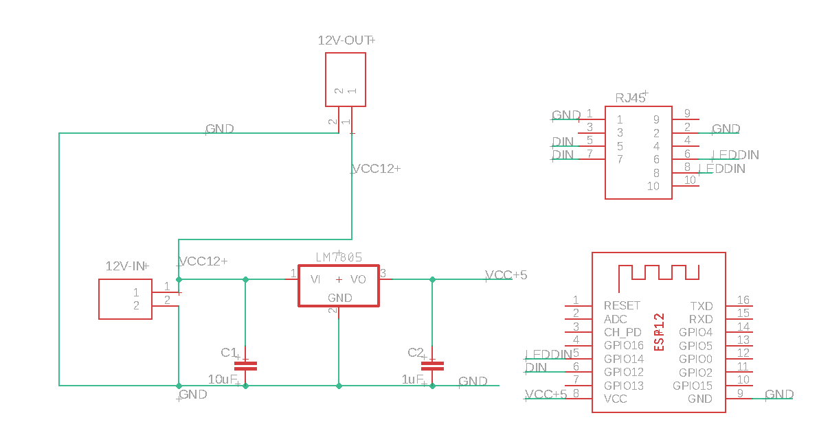
Here is my schematic:

enter image description here

  • Din: Connect to DIN WS2812B
  • LEDDIN: PWM pin dim 12 V led
  • I use LM7805 to convert 12 V dc to 5 V DC to power ESP8266
  • 12 V-out to power 12 V LED

Part Detail:

\$\endgroup\$
8
  • 3
    \$\begingroup\$ You're described your setup & goal ... so what is your question? \$\endgroup\$
    – brhans
    Commented Feb 20, 2022 at 17:33
  • 1
    \$\begingroup\$ Hi, Barry, welcome to the site. You've given us some good information about your setup so far, and what your goal is, but you haven't actually asked us a question. Please edit your question (there's a little edit link at the bottom) to include one. \$\endgroup\$
    – Polynomial
    Commented Feb 20, 2022 at 17:41
  • 1
    \$\begingroup\$ @BarryAllen Why you ask what you can do? What have you already done and does it not work? \$\endgroup\$
    – Justme
    Commented Feb 22, 2022 at 8:41
  • 1
    \$\begingroup\$ Just connect it? \$\endgroup\$
    – winny
    Commented Feb 22, 2022 at 8:45
  • 1
    \$\begingroup\$ I apologize for not being more explicit in the first place. I simply updated my question to include more information about my setup. Thank you. \$\endgroup\$ Commented Feb 22, 2022 at 9:19

3 Answers 3

1
\$\begingroup\$

Problem: WS2812B requires 5V logic level signals on the data pins. ESP outputs 3V3 logic levels. So it doesn't work.

Solution: use any 74HCT logic gate powered from 5V as level translator. It will correctly read 3V3 logic levels, and output 5V levels. Pick any 74HCT you want, like buffer, AND, OR, etc. It should not be inverting, though.

Problem: MOSFET doesn't work.

LM7805 isn't a MOSFET, it's a voltage regulator. I assume it's a typo, and you're using an actual MOSFET. If it is not designed for 3V3 gate drive, it will not work when driven from an ESP GPIO pin.

Solution: use another gate in the 74HCT chip as a 3V3 to 5V converter, and drive a 5V logic level MOSFET with it.

\$\endgroup\$
5
  • \$\begingroup\$ WS2812B datasheet states that High Voltage Input Vih min = 2.7V. Also, according to OP schematic he doesn't "drives" it from ESP8266, LEDDIN are just floating. But you probably right here on the part that OP tries to use it as a driving MOSFET, when the schematic are incorrect. \$\endgroup\$
    – NStorm
    Commented Feb 22, 2022 at 12:08
  • \$\begingroup\$ Well, there are seems to be a different versions of either WS2812B datasheets or IC itself. I've the one labeled "V5" here instructables.com/Moodiest-Display and it mentions Vih(min) = 2.7V. While others put it as 0.7 Vdd. \$\endgroup\$
    – NStorm
    Commented Feb 22, 2022 at 12:16
  • \$\begingroup\$ Ah, that explains it. Datasheet for mine says 0.7VDD. \$\endgroup\$
    – bobflux
    Commented Feb 22, 2022 at 12:44
  • \$\begingroup\$ @bobflux sorry for the unclear info, the LEDDIN pin is connected to a MOSFET(IRFZ44N), and yes LM7805 isn't a MOSFET \$\endgroup\$ Commented Feb 22, 2022 at 14:48
  • 1
    \$\begingroup\$ OK! IRFZ44 needs 10V gate drive to fully turn on, won't work with 3V3 or 5V. You need another MOSFET. \$\endgroup\$
    – bobflux
    Commented Feb 22, 2022 at 17:00
0
\$\begingroup\$

Signal Integrity maybe

Try to remove the 10ft cable and directly connect the LED to your ESP. If the system works, then the issue is the cable.

A cat 5 is a twisted cable. Thus you can't just pick random wire and hope it works.

I would try the following:

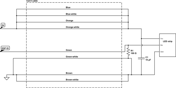
  1. Use a pair for the signal and its return current. Put your signal on the green wire and GND on the green-white wire. for instance.
  2. Properly terminate the transmission line. Add a ~100 Ohm resistor across the green and green-white wire at the led end of the cable.
  3. Add an additional decoupling caps
  4. Use all the remaining wires for the power

schematic

simulate this circuit – Schematic created using CircuitLab

\$\endgroup\$
0
\$\begingroup\$

After searching around I found this solution the author uses RS-422/485 drivers and receivers to control ws2812b

\$\endgroup\$

Your Answer

By clicking “Post Your Answer”, you agree to our terms of service and acknowledge you have read our privacy policy.

Not the answer you're looking for? Browse other questions tagged or ask your own question.