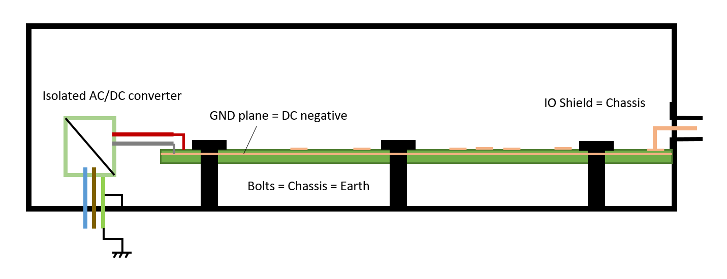
Although there are various suggestions around for how to connect circuit GND to the earthed chassis (say, the chassis has a point-to-point resistance of around 1 mΩ) in devices, there seem to be two rather common cases (explained below the figure) used in the following situation:
 (EMI filtering near IO and PSU off-board connections omitted for clarity)
Bolt circuit ground and chassis together at as many places as possible, i.e. all the shielded connecters, all the mounting screws. The circuit ground and chassis become the same node.
Still connect chassis and circuit ground but treat them as two separate nodes. They are connected at only one point DC-wise (either near the IO or near power). The IO shields and mounting holes connect to chassis directly, the ESD circuitry also connects to chassis. In addition, the chassis should be thoroughly AC-coupled at various points to circuit GND (mounting holes and especially near the IO) to allow for high frequency return currents to have very small loops and make the design EMC-fit. The DC leads from the converter should be also AC-coupled to the chassis to provide common-mode return paths.
Clearly the first approach is the simpler and the lower impedance (coupling-wise) one. I have used the second approach and it has been fine, but I wonder now whether it is worth the hassle.
My question is what are the drawbacks of the first approach (GND = chassis) that make the second approach ever worthwile, in particular for EMC and for safety. I am not interested in potential drawbacks for analog precision, as I believe that both these design are not ideal in this respect and single-ended analog return currents must never share the same medium with any other return currents for highest precision.
Some of my thoughts about the drawbacks of the first approach are following, and I would be happy if these could be also assessed in an answer:
The first design would have various low frequency circuit return currents flowing through the chassis walls, e.g. power supply return currents. As a result, power supply voltages would slightly vary due to the common-impendace coupling. This could cause digital signal integrity issues and jitter. But most computer hardware seems to be fine, so probably a non-issue.
The low frequency return currents in the chassis would impose a slight voltage in the chassis wall. Only a few mV even for very large currents. But if some part of the chassis would obtain a second low impedance earth connection, some current could escape there, potentially through the installation wiring and cause a residual current fault? Worse still, the current through this second earth connection could be high enough to be a fire hazard. Is this a problem for devices with very large internal return currents?
When subjecting the second design to an ESD strike on the IO shields, the current goes straight into earth. For the first design where GND=chassis, the ESD returns through both chassis and the GND plane which might cause trouble. But I think, as the GND plane impedance is also very low, this should be inconsequential?! Again: computer hardware seems to completely fine using this approach.
