2
\$\begingroup\$

I need to have a relay turn on/off power to a circuit, with the push of a button.

The way this will work is, when the button is pressed, power will be stopped to the circuit.

If it is pressed again, power will be restored.

I am new to relays, and I am not sure what a circuit like that should look. Seeing similar projects online, I saw projects where power can be enabled when the button is pressed.

However, in projects like these the power was on, only when the button was being pressed. There was no memory involved.

What I want is the button to enable the power on/off.

Also, is a diode always required when using relays in the circuit?

The power is 12 V. The circuit indeed runs at 12 V. I get the 12 V from a transformer. The output of the transformer is fed to a barrel jack switch (like the big black one the Arduino has). There I have my 12 V. Then the 12 V should go into this board. But I have a button that when pressed will shut down power to the board, in order to turn off the servos immediately - in case of an emergency.

This is why I have to have a latching relay, so that it retains memory (when button is pressed once - the circuit is powered on/off). However, since this is the first time working with relays, I am not sure how I should wire the whole thing. Also, I am not sure if a diode should be used - or if it is not needed and is implemented inside the relay.

\$\endgroup\$
10
  • 3
    \$\begingroup\$ Just use a toggling pushbutton button. I prefer a toggle lever, personally. \$\endgroup\$
    – DKNguyen
    Commented Feb 22, 2022 at 15:42
  • 1
    \$\begingroup\$ There are relays that toggle each time they're activated. Would that work for you, or are you treating it as an exercise in relay logic? digikey.com/en/products/filter/power-relays-over-2-amps/… digikey.com/en/products/filter/signal-relays-up-to-2-amps/… \$\endgroup\$ Commented Feb 22, 2022 at 15:51
  • \$\begingroup\$ @Yes that would work. So just the toggle and the relay? Is there a need for diodes or other circuitry? I have never worked with relays before. \$\endgroup\$ Commented Feb 22, 2022 at 15:52
  • \$\begingroup\$ A flyback diode across the coil is always preferred, to prevent the current from causing arcs and damaging other parts of the circuit. Other than that, yes, each time you activate the coil (momentarily) the relay will toggle from one state to the other. \$\endgroup\$ Commented Feb 22, 2022 at 15:54
  • \$\begingroup\$ @CristobolPolychronopolis That's not how a single-coil latching relay works. You have to apply current through the coil in one direction to turn it on, and the opposite direction to turn it off. \$\endgroup\$
    – Hearth
    Commented Feb 22, 2022 at 16:00

3 Answers 3

7
\$\begingroup\$

A simple low-cost solution would be to just use a push-to-on / push-to-off switch to control the power.

enter image description here

There would be no need for a relay.

\$\endgroup\$
3
  • \$\begingroup\$ Nice to see the simplest solution presented. This isn't overengineering or under-engineering -- it's elegant engineering! \$\endgroup\$ Commented Feb 23, 2022 at 6:39
  • \$\begingroup\$ Thank you, but how will it be connected to the relay? \$\endgroup\$ Commented Feb 23, 2022 at 8:34
  • \$\begingroup\$ user1584421, No relay would be required. I've edited my answer accordingly. \$\endgroup\$
    – vu2nan
    Commented Feb 23, 2022 at 10:27
2
\$\begingroup\$

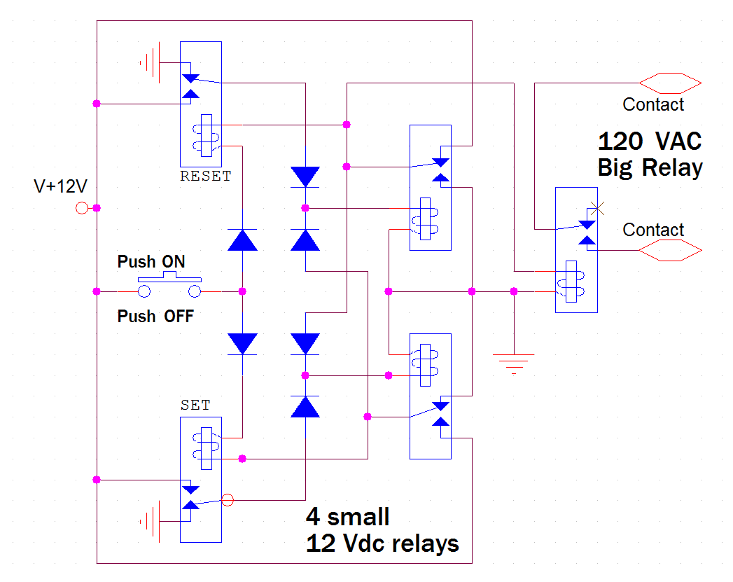
Here is my proposed solution. It require 4 small SPDT relays ( 5 or 12 V ) and 1 big 120VAC SPST contact relay with 12Vdc coil if you need lots of switching power. Need also 6 passive diodes. Basically, it is a mechanical RS flip/flop. No complicated electronic but require a bit of wiring. 5 or 12V could be supplied with a cheap plugin power block enter image description here

\$\endgroup\$
1
\$\begingroup\$

What I want is the button to enable the power on/off.

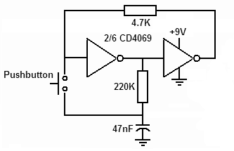
You can make a push-button do what you want by using this circuit: -

enter image description here

Image from this Q and A.

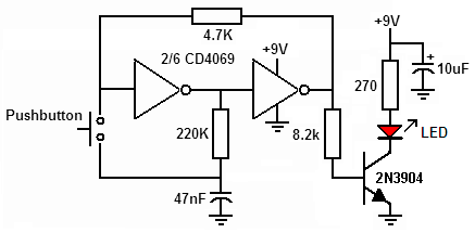
Then, on the logic output of the 2nd inverter, add a transistor for controlling the coil current for the relay. A bit like this (but instead of the LED and 29=70 Ω resistor you fit the coil: -

enter image description here

Image from this Q and A. Your coil supply isn't limited by the supply to the latching inverters either.

Also, is a diode always required when using relays in the circuit?

Yes, you'll need a reverse acting diode across the coil.

\$\endgroup\$
4
  • \$\begingroup\$ Thank you very much! But a comment on my question suggested toggle buttons. I think this would make the circuit far simpler. If you would like, you can edit the question, and add the toggle button circuitry as well. \$\endgroup\$ Commented Feb 22, 2022 at 15:53
  • \$\begingroup\$ @user1584421 I am not recommending that route; I'm recommending the above route. \$\endgroup\$
    – Andy aka
    Commented Feb 22, 2022 at 15:55
  • \$\begingroup\$ @user1584421 I'm also not recommending the relay (added to your question) for two reasons; (a) it comes from Shamazon and they are not a quality route for electronic components that I can ever recommend until they get their brown-stuff together in a far greater way and (b) there is no data sheet for the part hence, if you can work out what the coil resistance is then good luck to you. \$\endgroup\$
    – Andy aka
    Commented Feb 22, 2022 at 16:21
  • \$\begingroup\$ Thank you very much for your input. I am a complete newbie to relays. Searching more - after i posted the question - i found out about latching relays, that preserve the state. So i think i will go with these. \$\endgroup\$ Commented Feb 22, 2022 at 16:26

Your Answer

By clicking “Post Your Answer”, you agree to our terms of service and acknowledge you have read our privacy policy.

Not the answer you're looking for? Browse other questions tagged or ask your own question.