0
\$\begingroup\$

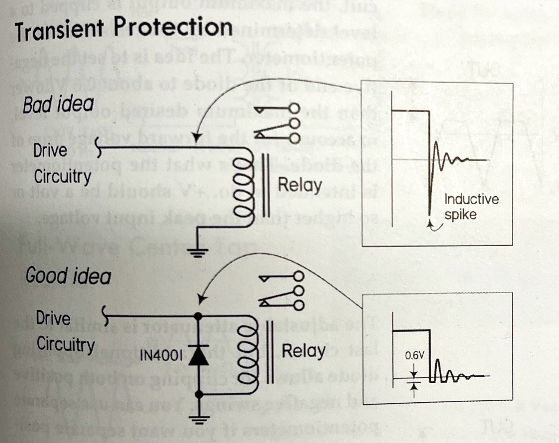
In the following picture captured from the book Practical Electronic for Inventors, it mentioned that there will be a huge negative voltage spike when the switch is suddenly switched off.

enter image description here

According to the blog here, the negative spike is due to the Ohm’s law: V=IR and as R is going to be very huge (the resistance of the air), given that the current should still be the same in the loop, so the voltage difference between the point prior to the inductor and the ground should be negative in order to conform to KVL (voltage source gain(battery)+ voltage drop in the gap (switch) + voltage gain in the inductor = 0).

In the picture, the voltage waveform also shows that after the negative voltage spike, it revives to positive and then drops to negative again, over and over until the energy dissipates.

My question is, why does the voltage revive back to the positive after the first negative voltage spike? And why is there a second and even the following negative damped spikes?

\$\endgroup\$

2 Answers 2

2
\$\begingroup\$

Ok, this is not so trivial but not so complex too. A keyword here is - Resoncance. There is some capacitance of driver circuitry, trace-PCB-ground circuitry, inter-winding capacitance. It creates a series resonant circuit with winding of your relay.

Pleas note an interesting fact: diodes when reverse polarized also show some not negligible capacitance (you can search for interesting element called Varactor to read more about this effect used for construction VCO - voltage controlled oscillators). It is caused by creation of a depletion zone in PN junction which acts as capacitor. So its not like diode will dampen everything (it does NOT stop resonance that much), but it will significantly attenuate first spike created by inductor.

As a side note you can search for circuit called "snubber", which is used to dampen reverse impulses from more serious inductors (please remember that diodes are suffering from high surge current in circuit from your post - it might be well in their Maximum Allowed Ratings, but you have to always verify that in datasheet).

\$\endgroup\$
1
  • \$\begingroup\$ It's actually L//C// high R not series resonance where Q = R/X(f) is near 0 when diode conducts (overdamped) and very high when not. But if using a series switch with an arc, then it different \$\endgroup\$
    – D.A.S.
    Commented Feb 23, 2022 at 17:53
2
\$\begingroup\$

The oscillatory nature of the spike shown in your diagrams isn't explained very well it seems AND, in most situations will be barely noticeable when the diode is fitted as per the 2nd diagram in the picture. The short story is ignore that oscillation until you have got to grips with what are called resonant tuned circuits.

If you want the slightly longer story; parasitic capacitance in the coil and the coil's own inductance cause a decaying oscillation when the coil is open-circuited. A capacitor and an inductor form a resonant circuit and can make this oscillation happen but, in most situations it will be not be noticed when the diode is fitted.

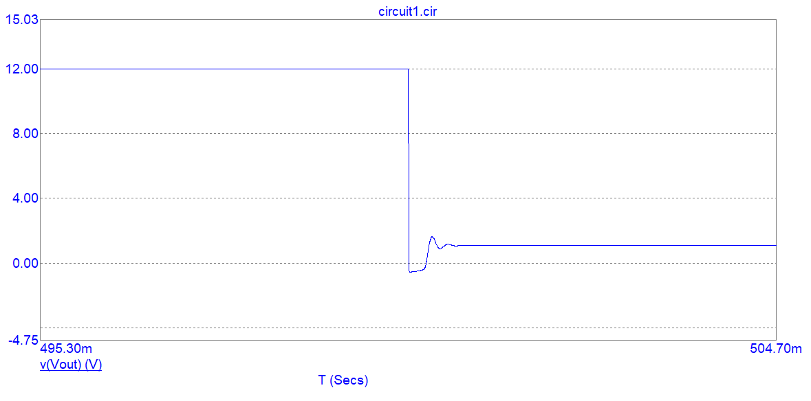
With diode fitted and a coil of 1 henry and 10 kΩ DC resistance: -

enter image description here

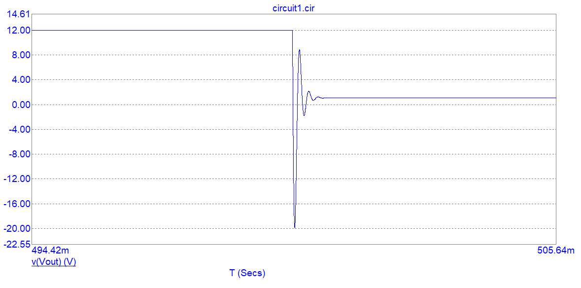
To make the oscillation clearer (exaggerated) I've added 1 nF in parallel with the coil although, in most situations, that would be about ten times more excessive that the parasitic capacitance.

Without the diode: -

enter image description here

\$\endgroup\$

Your Answer

By clicking “Post Your Answer”, you agree to our terms of service and acknowledge you have read our privacy policy.

Not the answer you're looking for? Browse other questions tagged or ask your own question.