0
\$\begingroup\$

After looking at several circuit diagrams and their actual implementation, I found that the position of the parts is not considered in the diagram. Is there any reason for this?

If all parts are arranged on a flat ground (i.e. 2D) would it be theoretically possible?

I clearly see the problem if the parts are organized in a 3D structure (e.g. a machine) but not in a 2D way.

What is the right type of diagram that provides a circuit diagram with the corresponding position?

Mostly all the components of the machine that I want to represent are relatively simple ones (motors, compressors, sensors etc.) and connected directly to the inputs and outputs of one controller. This means there is nothing between controller and component. What is the value of using a circuit diagram instead using a simple table?

\$\endgroup\$
6
  • 1
    \$\begingroup\$ A layout, probably... \$\endgroup\$
    – Mike
    Commented Mar 1, 2022 at 11:12
  • 4
    \$\begingroup\$ The purpose of a circuit diagram is usually to convey to the viewer the electrical functioning of the circuit. if they had to include physical placement of components (which is a matter for the constructor), they would be much harder to understand, and probably look like a crazy spider web. \$\endgroup\$ Commented Mar 1, 2022 at 11:14
  • \$\begingroup\$ @MichaelHarvey, thanks! As I understand you right: a circuit diagram is just to represent how the electrical circuit works, and not how the components of that machine are arranged to provide the machine's function. \$\endgroup\$ Commented Mar 1, 2022 at 11:26
  • \$\begingroup\$ If you were building an audio amplifier (for example), you might want to take multiple connections to ground at the same place, to avoid hum or other loops, but the circuit diagram will probably show them all going separately to the bottom ground or common line. Failure to appreciate this sort of thing, can be reason for problems, maybe if a breadboard is being used for a prototype. RF even more so. \$\endgroup\$ Commented Mar 1, 2022 at 11:32
  • \$\begingroup\$ To answer the addition to the question, sounds more like a functional diagram then a circuit. Could use diagrams.net . Super easy to draw quick diagrams. Its free and they have a library of high-level electronic symbols for components but industrial stuff (rotating equipment) as well. Just beware that larger drawings get difficult to manage because there is 0 automation. This is really an quick-and-dirty tool. For design of industrial machines there must exist special cad packages but not one that I know of. Perhaps someone knows of this? \$\endgroup\$
    – Thijs
    Commented Mar 1, 2022 at 11:34

5 Answers 5

4
\$\begingroup\$

What is the right type of diagram that provides a circuit diagram with the corresponding position?

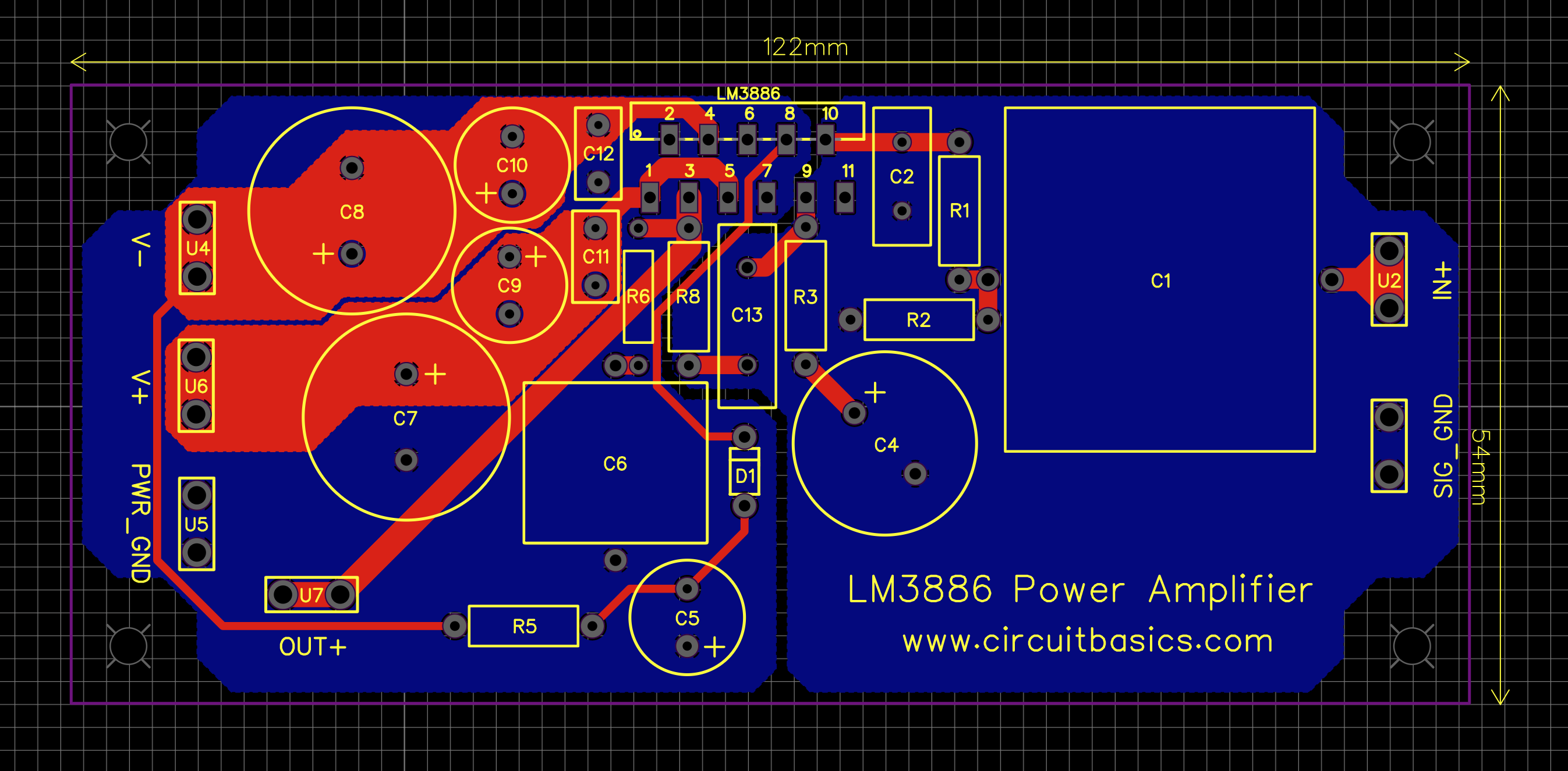
The "right type of diagram" is the PCB layout and one of the several layered images that the PCB software produces. It should never be the intent that a schematic diagram (aka circuit diagram) indicates physical component positions.

Schematic diagrams and PCB layout diagrams are pretty much interlinked within one software tool so, when you say this: -

I found that the position of the parts is not considered in the diagram. Is there any reason for this?

I have to say that it appears that you haven't looked in the right places.

\$\endgroup\$
3
  • \$\begingroup\$ Thank you for the fast answer! I was not aware of PCB (Printed Circuit Board) but when I looked at these diagrams, those are more for boards. I want to represent a machine consisting of several motors, compressors, etc. . Is this type of diagram also used for this type of task? Or there are other ones? What do you recommend? Thanks in advance! \$\endgroup\$ Commented Mar 1, 2022 at 11:20
  • \$\begingroup\$ @user3352632 you've asked a few electronic questions so far so I'm a little confused here as to why you were not more specific in your question (too late now of course). I think you may be referring to single-line diagrams (schematic) and, in your edit you ask about tables vs diagrams. Firstly, do not evolve this question further; once you have answers, it is bad form to move the goalposts of your question but, for this one-time, I'll try and answer. If the SLDs are simple then of course a table can suffice; it all depends on how much information you wish to put on the diagram. \$\endgroup\$
    – Andy aka
    Commented Mar 1, 2022 at 11:36
  • \$\begingroup\$ Single line diagrams from wiki FYI. \$\endgroup\$
    – Andy aka
    Commented Mar 1, 2022 at 11:37
3
\$\begingroup\$

A 'schematic' is just that. It's a purely symbolic representation of the circuit that shows the scheme of the circuit. That's parts and logical interconnections ('nets').

A schematic drawing contains no mechanical information.

Instead, each part symbol has a footprint associated with it that contains the shape on the PCB needed for the part but no location information.

The PCB layout is a separate and secondary exercise after schematic capture. It is the files/drawings produced by layout that carry all mechanical information needed to make, assemble, inspect and use the board.

Mechanical information may additionally be conveyed in text notes on the schematic but these are for critical or noteworthy items only. Part symbols can show mechanical information about the part but few do. In nearly all schematics, these would be carrying a tiny fraction of the total mechanical info for the board.

Mechanical requirements for PCB track distancing, thickness etc can be embedded in the schematic files. This information is used in PCB layout and only results in mechanical dimensions and positions during PCB layout. Beyond global defaults selected for the board design, this information is only of particularly use for higher-frequency transmission line tracks and tracks carrying higher currents and voltages.

\$\endgroup\$
2
\$\begingroup\$

What is the right type of diagram that provides a circuit diagram with the corresponding position?

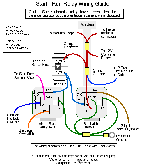
Generally speaking, it's called a "wiring diagram".

For example, these images".

For example:

Wiring diagram from Wikipedia {Wikipedia}

In the specific case of a PCB, it's called a "PCB layout"

For example:

PCB layout source

\$\endgroup\$
1
\$\begingroup\$

I found that the position of the parts is not considered in the diagram. Is there any reason for this?

Yes - there is a good reason:

There are always different ways to realize such a circuit diagram in hardware. More than that, passive and active parts are available in different forms and packages (dependent on manufactureres). Therefore, it would be not a good decision to require a particular layout from the beginning.

\$\endgroup\$
-1
\$\begingroup\$

As an industrial maintenance electrician, and the person who will be working on your machine when the line has stopped because of it and there are 100 people getting more mad by the minute, it's a ONE LINE diagram that just show the controls... ie: output 0:1 starts motor 1, or input 0:4 is end of conveyor stop sensor.

I cannot explain to you the importance of these diagrams, as most machines are different and most maintenance guys cannot get online with a PLC... so thank you for caring and honestly, we would buy more machines from you if you put those simple words like end of conveyor stop sensor in your one line diagrams.

Too many engineers get lazy and use default definitions on these inputs and outputs that really makes your machine not as good as someone who just added this extra step.

\$\endgroup\$

Your Answer

By clicking “Post Your Answer”, you agree to our terms of service and acknowledge you have read our privacy policy.

Not the answer you're looking for? Browse other questions tagged or ask your own question.