3
\$\begingroup\$

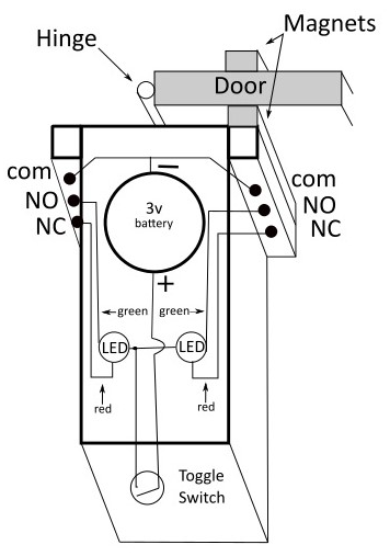
With minimal electronics knowledge, I'm trying to make a circuit using 2 bicolor LED (red 2.0V, green 3.0v, common anode), a 3v battery (CR 1220 lithium), a couple of reed switches and a toggle switch to power the circuit off and on. It involves a 180 degree swinging door with reed switch magnets mounted on it.

When the door is opened to either side, the bicolor LED on that side is green and the LED on the other side is red and visa versa.

When the magnets are not near either reed switch, both red leds are lit. I can't get the green led to light. I figured the 3v battery couldn't handle the draw for the red and green LEDs to be lit at the same time because the green LED is rated at 3v and the red is rated at 2v. So I put another 3v battery in series with the first battery. Still wouldn't light the green LED. I then added a 430 ohm resistor included with the LEDs, to the + pole of the battery. Didn't help.

I know I could split the circuit in two, with a 3v battery for each side and use a DPST switch to toggle power for both circuits, but was just wondering if there was a simple solution to keep it as one circuit. Sorry about the non-technical drawing, hope it conveys the basic idea.

enter image description here

\$\endgroup\$

2 Answers 2

2
\$\begingroup\$

A 2V diode in parallel with a 3V diode will cause the node to pull down so much that the 3V diode will not get enough voltage or current. Especially with a coin cell that has a high internal resistace (which is likely why you didn't blow the red led out).

By adding a resistor to each diode cathode, you force an equilibrium where both diodes + resistor see the full voltage.

The red diodes will get a bigger resistor due to the voltage difference.

That said using a 3V coin cell will depending on the current pulled not last long at all.

\$\endgroup\$
3
  • \$\begingroup\$ I thing you bought a bi-color LED that already had its green LED burned out or you did it before starting this project. \$\endgroup\$
    – Audioguru
    Commented Mar 6, 2022 at 20:53
  • \$\begingroup\$ @audio you mean op? \$\endgroup\$
    – Passerby
    Commented Mar 6, 2022 at 21:05
  • 1
    \$\begingroup\$ Yahoo! Thanks Passerby. I added 470 ohm resistors to the red cathodes and 430 ohm resistors to the green cathodes and voila! \$\endgroup\$
    – LDA
    Commented Mar 6, 2022 at 21:18
3
\$\begingroup\$

You need to add a resistor for each LED. In case if you have a coin cell which is a very weak battery, you might not damage the LED, but generally directly connecting a LED to a voltage source like a battery is just plain wrong.

If you parallel 2V and 3V LED by directly connecting them to a 3V coin cell battery, the 2V LED will hog all the current and bring the battery voltage down to 2V, so there is not enough voltage for the 3V LED to light up.

\$\endgroup\$
2
  • \$\begingroup\$ Thanks Justme. You were absolutely right. Works now. \$\endgroup\$
    – LDA
    Commented Mar 6, 2022 at 21:21
  • \$\begingroup\$ "generally directly connecting a LED to a voltage source like a battery is just plain wrong" It's worth mentioning that, although you are right in general, there are plenty of gadgets that directly power a single LED (especially white ones) from a CR2032 (or similar primary lithium) 3V battery. They get away without any issues because the small battery has enough internal resistance that an external limiting resistor is usually not needed. \$\endgroup\$ Commented Mar 7, 2022 at 9:37

Your Answer

By clicking “Post Your Answer”, you agree to our terms of service and acknowledge you have read our privacy policy.

Not the answer you're looking for? Browse other questions tagged or ask your own question.