0
\$\begingroup\$

I recently saw a circuit that left the NMOS's source open without connecting to any terminal.

Gate: A pull-up 10 kΩ resistor to 3.3 V.
Drain: A pull-up 10 kΩ resistor to 3.3 V.
Source: Nothing connected.

The source has a fixed 2.2 V observed by the oscilloscope.

The MOSFET's Vth is 1 V (min.) to 2.5 V (max.) according to its datasheet.

I varied the gate pull-up voltage source from 3.3 V to 2.5 V and 4 V and the voltage on the source side became 1.5 V and 2.9 V. It seems to me the voltage on the source is Vgate minus Vth(min).

Does anyone know why the source is left open but still has a fixed voltage level?

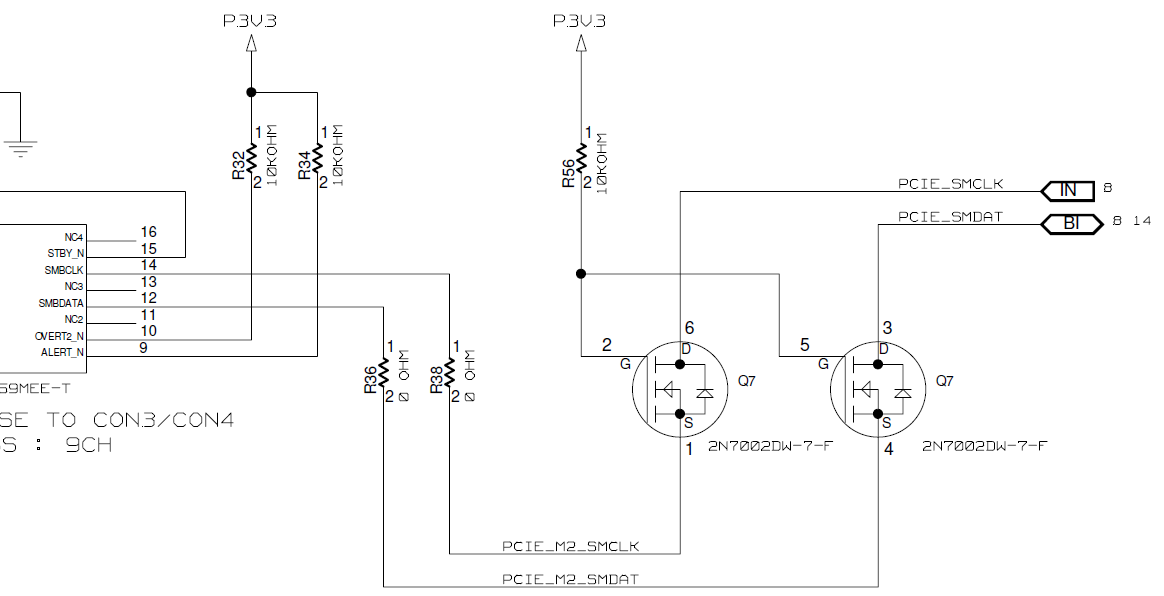
*I attached the circuit in the below. I removed R38 & R36 and still see Vsource = 2.2V as stated above. Q7 is the N-MOSFET. *There is a Pull-up resistor (10K) placed in other page for PCIE_SMCLK & PCIE_SMDAT.

enter image description here

\$\endgroup\$
5
  • \$\begingroup\$ You might want to show us this circuit? There’s the intrinsic diode that would be conducting that might explain the voltage. \$\endgroup\$
    – Kartman
    Commented Mar 21, 2022 at 10:58
  • \$\begingroup\$ @Kartman, I attached the circuit FYI. Thanks. \$\endgroup\$
    – Zac Chien
    Commented Mar 21, 2022 at 12:17
  • 1
    \$\begingroup\$ Also note that mosfets have a leakage current. This maybe in the range of uA. Coupled with the input resistance of the measurement device, a voltage divider is formed. Try warming up the mosfets to see if the measured voltage rises. If it does, then it’s a fair chance leakage is the culprit. \$\endgroup\$
    – Kartman
    Commented Mar 21, 2022 at 12:37
  • \$\begingroup\$ @Kartman, Do you mean if I didn't use the scope then there is no source voltage since the source is open (R38 removed)? Leakage current should not flow to the point that is open. \$\endgroup\$
    – Zac Chien
    Commented Mar 21, 2022 at 13:25
  • \$\begingroup\$ It's not leakage. Your MOSFETs leak far less than 1 µA when they are properly turned off. But your scope pulls the source towards ground and infact turns on the MOSFETs with a forward drop of \$V_{gs,th}\$. (Long explanation below) \$\endgroup\$
    – tobalt
    Commented Mar 21, 2022 at 15:48

1 Answer 1

1
\$\begingroup\$

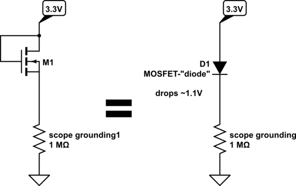
That would essentially be a "diode-connected" MOSFET (akin to the diode-connected BJT) with gate and drain shorted. This is the equivalent circuit:

schematic

simulate this circuit – Schematic created using CircuitLab

In this circuit, the source is not able to reach at anything lower than \$3.3 - V_{gs,th}\$, clamped by the diode-connected MOSFET.

Your scope probe is grounded via a large resistance (1 Megaohm probably). That way you pull the source to ground, and the diode-connected MOSFET turns on, because the gate-source voltage becomes suddenly 3.3 V. The current through the MOSFET will quickly raise the source voltage to the equilibrium point. That means the "diode" will drop its regular forward voltage which is roughly \$V_{gs,th}\$ and you indeed read a voltage that is 1.1V lower than the gate voltage. That drop voltage is on the low end of the specced \$V_{gs,th}\$ range because the current through the scope probe is pretty low at only a few µAs.

\$\endgroup\$
1
  • \$\begingroup\$ Thank you. It is very helpful. Let me do some experiments. \$\endgroup\$
    – Zac Chien
    Commented Mar 23, 2022 at 1:10

Your Answer

By clicking “Post Your Answer”, you agree to our terms of service and acknowledge you have read our privacy policy.

Not the answer you're looking for? Browse other questions tagged or ask your own question.