0
\$\begingroup\$

I am trying to generate a 30Hz triangle wave from a MSP430FR5994 MCU (specifically with the MSP430FR5994 Development Kit. The reason why I am trying to do this is for a Continuous Wave, Frequency Modulated sensors, and I need the triangle wave to modulate a VCO (I used the CD4046) for the output signal, then compare the output triangle wave with a demodulated input from the returning signal. And because my MCU doesn't come with an in-build DAC.

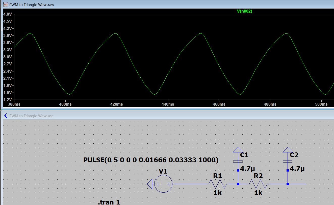
Simulations with LTSpice suggest that using the PWM as a square wave then rectifying that wave to a triangle wave yields this result. Since for my purposes, I need the triangle wave to remain as linear in its rate of change as possible, I don't think this method is viable.

enter image description here

Instead, I'm going to try to use the PWM as a DAC, using it like how other people program their DACs to be undervolted DC signals, only this time the output signal will be varying. Low pass filter to clear out the PWM signals.

Does that seem like a reasonable way of doing things? Or should I just buy a DAC IC? Learning to interface with a DAC IC seems like more challenging to my untrained eyes. If any more information is needed, please let me know.

\$\endgroup\$
5
  • \$\begingroup\$ I am using a CD4046 for both modulation and demodulation. I didn't think that was relevant information, but I'll edit that in. I need the triangle wave to vary the VCO frequency on the CD4046. \$\endgroup\$ Commented Mar 27, 2022 at 14:29
  • \$\begingroup\$ Ok. Do you need "extra" straight lines for driving VCO? If yes, use a circuit made by "integrator" and Schmidt circuit (positive feedback). \$\endgroup\$
    – Antonio51
    Commented Mar 27, 2022 at 15:08
  • \$\begingroup\$ @Antonio51 Sorry if this seems very basic, but what exactly do you mean? I do need "extra" straight lines for driving a VCO. \$\endgroup\$ Commented Mar 27, 2022 at 15:36
  • \$\begingroup\$ I mean as "linear" as possible. Will add example of circuit . \$\endgroup\$
    – Antonio51
    Commented Mar 27, 2022 at 15:44
  • \$\begingroup\$ I guess it is for "distance" or "altitude" measurement? \$\endgroup\$
    – Antonio51
    Commented Mar 27, 2022 at 16:20

3 Answers 3

1
\$\begingroup\$

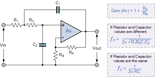
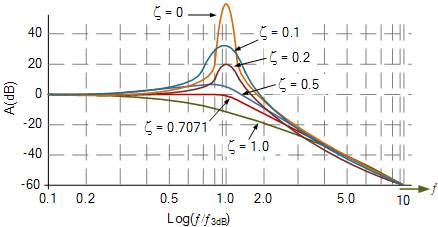
You want to have the PWM frequency as high as possible. (or as far away as possible in frequency from the triangle wave) enter image description here There is a game to play where the filter needs to block the PWM frequency and pass the triangle. If the filter is too fast the PWM comes through and the triangle looks good. Or if the filter is too slow the triangle is distorted.

I normally set Ra=short, Rb=open I like to set Q=0.5 to 0.7 https://www.electronics-tutorials.ws/filter/second-order-filters.html

enter image description here

\$\endgroup\$
0
\$\begingroup\$

Using a PWM with variable duty cycle and then low pass it should do the job, especially if you aim for an signal that is only 30Hz.

Let's suppose you use your MCU at its maximum frequency, Fclock=16MHz

If we go for example for Nquant=160 levels of quantification for the "output voltage", then we can set a PWM frequency of Fpwm=Fclock/Nquant=100 kHz

If you now put a low pass filter of let's say 1 kHz, you should be able to get a pretty good triangle without too much oscilation due to the PWM

\$\endgroup\$
0
\$\begingroup\$

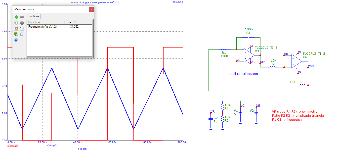
Example of very "linear" triangle-square generator.
Be sure using rail-to-rail opamp.

enter image description here

\$\endgroup\$
2
  • \$\begingroup\$ What model Op-Amps are you using in the simulation? I wanna test it in LTSpice before making a decision. \$\endgroup\$ Commented Mar 27, 2022 at 19:47
  • \$\begingroup\$ Just use rail-to-rail opamp ... \$\endgroup\$
    – Antonio51
    Commented Mar 27, 2022 at 20:26

Your Answer

By clicking “Post Your Answer”, you agree to our terms of service and acknowledge you have read our privacy policy.

Not the answer you're looking for? Browse other questions tagged or ask your own question.