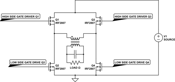
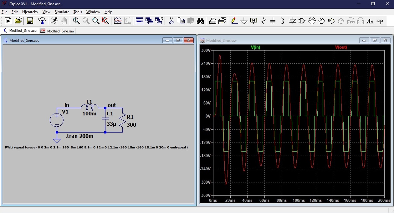
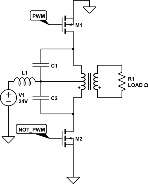
I am designing a 1500W inverter. With 24VDC input source and 220VAC 60Hz output voltage. I currently have the topology shown in circuit 1. This results in a square wave at 60Hz. But I need the output to be a pure sinusoid at 60Hz. The M1 and M2 mosfets are driven at 60Hz by PWM and NOT_PWM. To get the output with a pure sinusoid I thought of using an LC filter as shown in circuit 2. I started by trying to calculate the values of L and C through:
F=1/2*pi*sqrt(LC).
However, the values I obtained for L, considering the capacitance value of 10uF and F=60Hz, did not result in a sine wave.
Did I choose the wrong cutoff frequency?
I know that the mosfets switching mode should be SPWM with high frequency, but I have no way to change that at the moment. I have to make this work with switching the switches at 60Hz using LC filter.
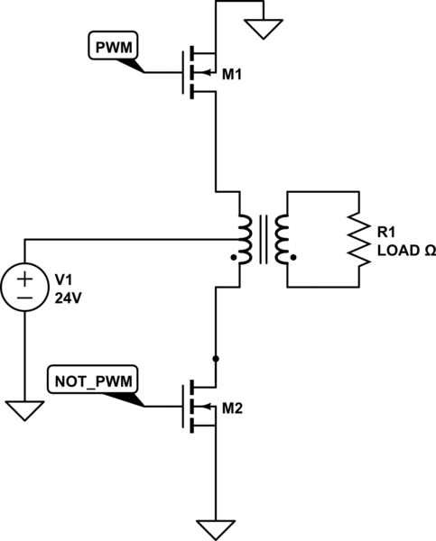
simulate this circuit – Schematic created using CircuitLab
EDIT
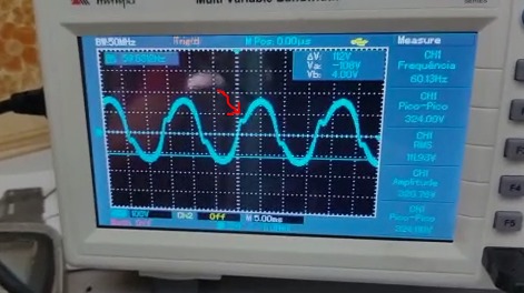
I would like to tell you that I managed to do my project. But it was necessary to change the project topology. I decided to use a full bridge and not a push pull. To make the sine wave I use a sinusoidal pwm signal (with duty cycle variable) and with frequency modulation at 60Hz.
Results in the image below.
