4
\$\begingroup\$

I own an old SONY radio / amplifier, model STR-7800SD. I opened it and I saw a resistor between one of the AC lines and the chassis. The funny thing is that it has a REVERSIBLE 2-prong plug! So, I found its service manual on hifiengine.com and here's the schematic for the power supply part: image.png I had assumed that the resistor was between neutral and chassis, but when I looked at the schematic, I saw that the power switch S11 would also be on the neutral. The other alternative is that the power switch is on the hot (phase), but then the 1 M-ohm resistor would be between phase and chassis! Or, perhaps it doesn't matter since the prong is reversible?
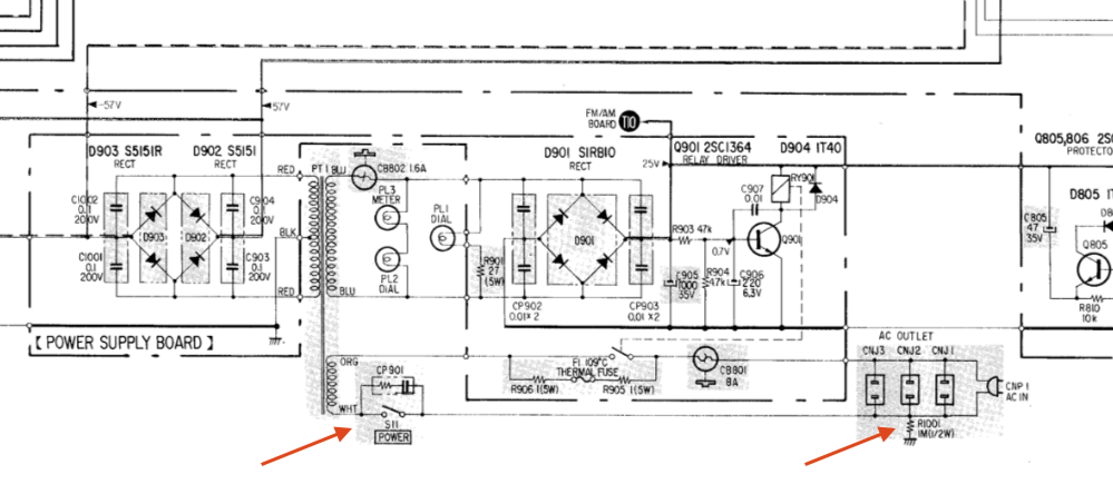
I have tried the following forums, but there doesn't seem to be any consensus:

https://audiokarma.org/forums/index.php?threads/3-6-megaohm-resistor-connects-where-on-ac-power-line.271819/

https://audiokarma.org/forums/index.php?threads/what-is-the-purpose-of-this-resistor.761888/

https://www.antiqueradios.com/forums/viewtopic.php?f=6&t=288638

https://audiokarma.org/forums/index.php?threads/resistor-from-live-ac-to-ground-sony-str-6065.820862/

To summarize:

  1. The plug is a 2-prong non-directional, not grounded. From a general user's perspective, there is no way to tell which prong is neutral and which one is hot, so it can be plugged in any direction. Of course, from an engineer's perspective, I can trace the prongs and wires back to the inside and see where they connect, then I can mark the prongs, but I don't think SONY intended for general users to do this.

  2. AFAIK, mains power switches are on the hot line (but it's not the case here)

  3. AFAIK, fuses are on the hot line (which is the case here)

My questions are:

  1. What is the purpose of the resistor?
  2. Is it safe to use this amplifier, no matter which way the plug is inserted into the outlet?
  3. If it's not safe, can it be made safer by replacing the 2-wire and 2-prong with a 3-wire and 3-prong, properly grounded plug that can only be inserted in one direction into a modern grounded outlet? Would I connect the hot to the top line marked ORG (orange), the neutral to the bottom line marked WHT (white), and the ground to the chassis? In this case, do I still need the resistor, or should I disconnect it?

Update 2022-04-03

The user manual and schematics (service manual) can be found here: https://www.hifiengine.com/manual_library/sony/str-7800sd.shtml but you need to sign up. Let me know if it is helpful to upload these somewhere.

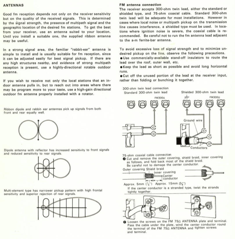
Regarding the mention of antenna in @david 's answer, I have uploaded a page from the user manual describing grounding of the antenna. Antenna grounding
\$\endgroup\$
3
  • \$\begingroup\$ Have you actually measured that the resistor is present in your device? Different market areas used to have some differences in the actual circuitry depending on where in the world the product will be sold. \$\endgroup\$
    – Justme
    Commented Apr 3, 2022 at 9:46
  • 1
    \$\begingroup\$ @Justme yes, I have measured the resistor to be 1 M-ohm \$\endgroup\$
    – SimplyTech
    Commented Apr 3, 2022 at 14:47
  • \$\begingroup\$ It would be downloadable if you could register to the website, but registrations are currently closed so nobody can register and download the schematics. You have to give a second source for them if you want someone look at them. \$\endgroup\$
    – Justme
    Commented Apr 3, 2022 at 15:12

2 Answers 2

2
\$\begingroup\$
  1. Yes. The device was fully compliant with all international safety rules and standards in place at that time. While those rules are much more restrictive now, they weren't terrible back then. The leakage current through R1001 is 120 uA in the US and 240 uA abroad. Both of these are less than 10% of the current (pun intended) limit of 3.5 mA. A typical trip value for GFCI outlets and breakers is 5 mA.

  2. Yes. Updating the device with contemporary wiring and grounding practices will improve it. I suggest that you wire it as you described, and leave in the resistor.

NOTE: You are dealing with lethal voltages and currents. No warranties expressed or implied.

\$\endgroup\$
1
\$\begingroup\$

The reason there is no consensus on the other boards you reference is that a resistor like that may serve one or many of several purposes.

  1. It will discharge induced or static voltage on the chassis. Particularly important if there is an antenna earthed on the chassis. (I don't see an antenna earthed on the chassis in this example)

  2. It will discharge power supply capacitance. Important if the power supply includes connected capacitance. (There is no directly connected capacitance shown in this example)

  3. It will prevent sparking of the power switch. Particularly important if the power supply includes connected inductance, or if the amplifier is connected to a radio receiver. Spark discharge can damage a switch, and may cause an audible thunk when the amplifier is connected to a radio receiver. (In this example, the connected transformer is unlikely to exhibit high inductance)

#1 is often radio receivers. #2 is often TV sets. #3 is often amplifiers. But it could be all or any.

\$\endgroup\$
1
  • 5
    \$\begingroup\$ Could you please explain how exactly it performs discharging of power supply capacitance, or how it prevents arcing of the power switch? With the schematics provided there is no way to deduce how it would manage to work as claimed. \$\endgroup\$
    – Justme
    Commented Apr 3, 2022 at 11:53

Your Answer

By clicking “Post Your Answer”, you agree to our terms of service and acknowledge you have read our privacy policy.

Not the answer you're looking for? Browse other questions tagged or ask your own question.