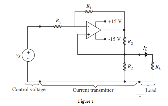
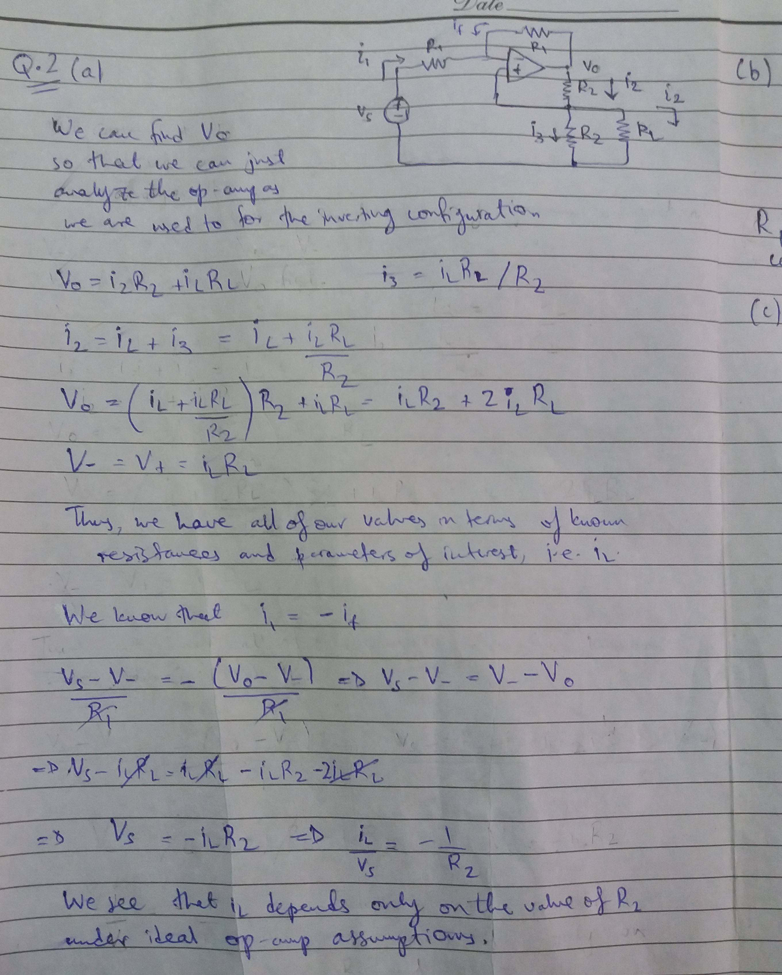
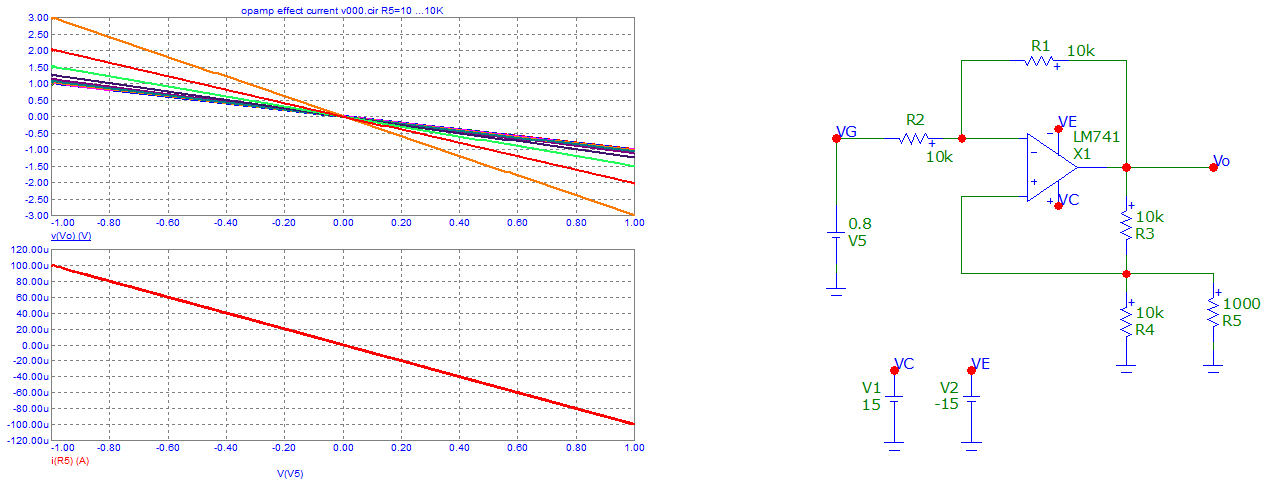
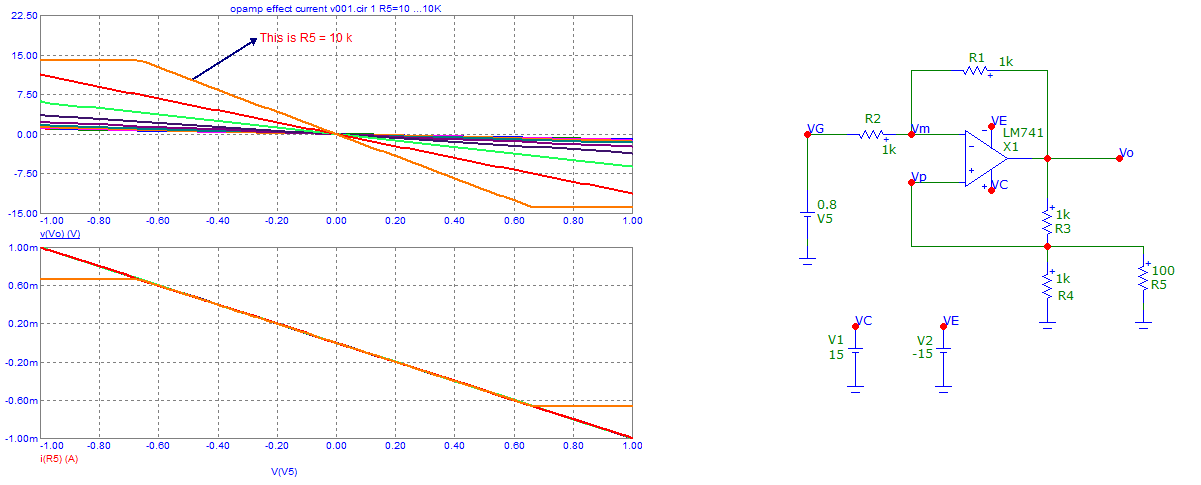
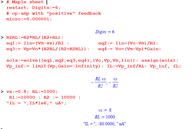
In my assignment, I want to study this current transmitter circuit shown in the figure 1. The goal of this circuit is to output a constant load current \$ i_L\$ (denoted by \$ I_L\$ in the diagram) controlled by \$ v_S\$ (operating within a certain range of \$ v_S\$ and \$ R_L\$). I derived the expression for relating \$ v_S\$ and \$i_L\$; that expression is (see figure 2) $$\dfrac{i_L}{v_S}=-\dfrac{1}{R_2}$$ The circuit simulation can be found on Multisim online here.
In the assignment question, the circuit is specified to work for $$|v_S|<1 V, R_L < 1k\Omega$$
However, the circuit does not behave according to the relation \$ i_L/v_S=-1/R_2\$ at those extreme conditions (being \$v_S=1 V, R_L = 1k\Omega\$), and it's probably because the op-amp output voltage \$ V_o\$ saturates at \$\pm \$15 V.
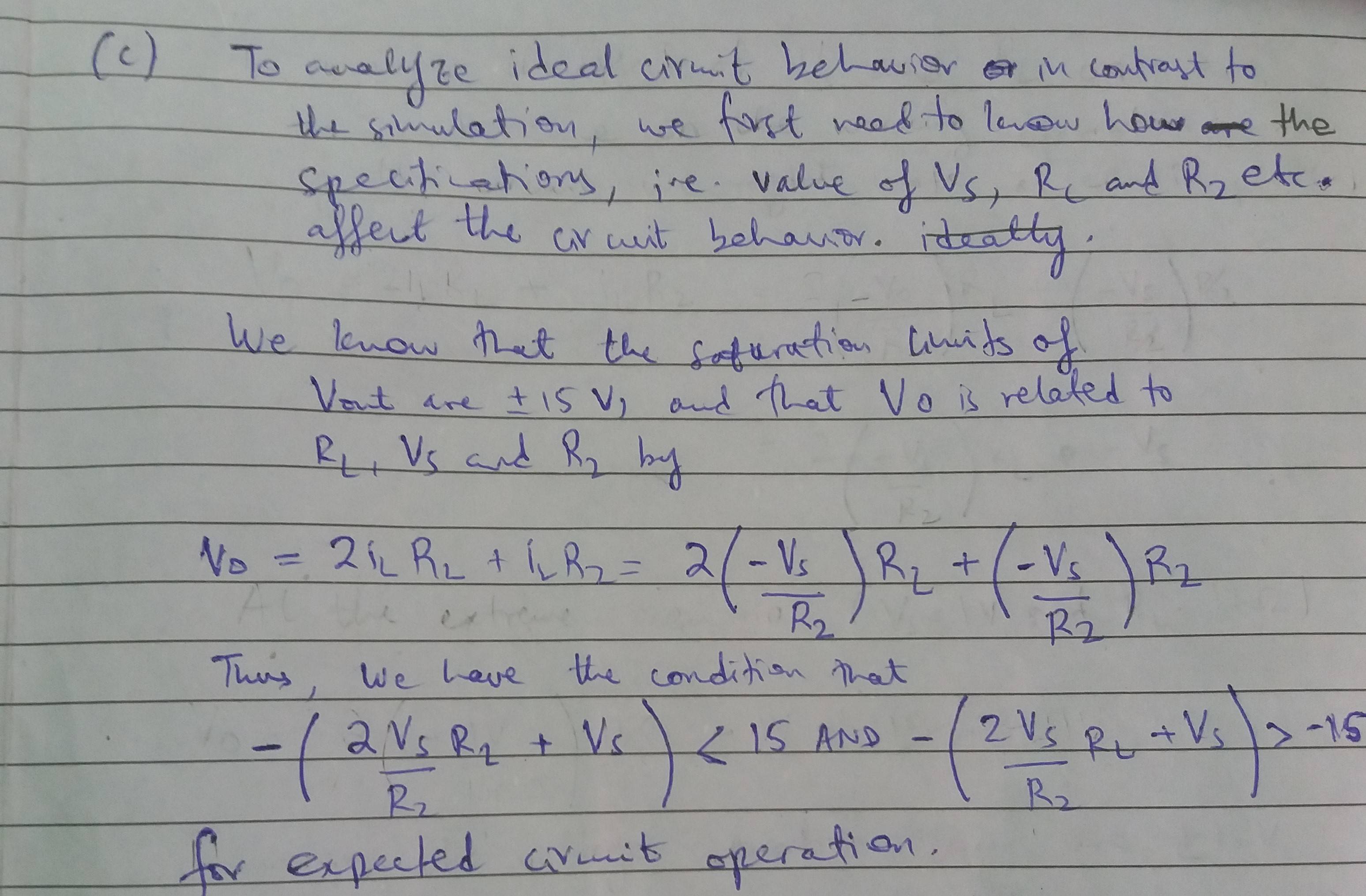
The expression that relates \$ V_o\$ with \$ v_S\$ and \$ R_L\$ is (see figure 3)
$$V_o = -(2 v_S \times R_L/R_2 + v_S)$$
And this must stay within saturation limits. At \$v_S=1 V, R_L = 1k\Omega, V_o=-21\$ V, so that explains the odd behavior there.
My concern is that, for a value of \$ V_o\$ within limits, specified by some \$ v_S\$ and \$ R_L\$ pair, the output is still anomalous. For example, when \$ v_S=0.8 V\$ and \$ R_L=300 \Omega\$, \$ V_o=-5.6 V\$, but simulated \$i_L=-5.66\$ mA as opposed to being -8 mA, and I can't think of any reason why we're deviating from the expected results.
