2
\$\begingroup\$

I have been trying to understand how to read a transistor datasheet properly, and to apply the ratings into my circuit to be able to calculate the needed resistor on the base leg.

I have a basic setup where my collector pin contains a 12V/3A LED supplied by a 12V power supply.

I am trying to control the power with a Raspberry Pi 4 Model b from the base leg.

What is needed to be known is that Raspberry's GPIO pin (3.3V logic) can handle 16mA at most, therefore, I employed a Darlington NPN transistor - BDX53C - to safely dim/amplify the LED's brightness with a PWM control.

I tried to get the basics of calculating the right amount of resistor to be able to safely control the environment without harming either the transistor or the Pi. I saw in this specific discussion and other various similar topics on the internet that people either calculate the potential difference in the base leg as 0.7V if it is a regular NPN or PNP transistor or 1.3 ~ 1.5V if it is a Darlington transistor.

Somehow, I couldn't find those values anywhere neither in my transistor datasheet nor in others. So my questions would be:

  1. Is the \$h_{FE}\$ value only needed to calculate the right resistor value in a setup? If not, are 0.7V and 1.5V potential differences nothing but a myth? Which variables represent those values in a transistor datasheet?
  2. What do the \$V_{CE(SAT)}\$ and \$V_{BE(SAT)}\$ variables represent in a transistor setup? Additionally, how can I find more specific values of them if they are needed, for instance, \$I_{C}=3A\$ but \$I_{B}=8mA\$?
  3. How can I assure myself that a transistor is suitable for my setup? For instance, how can I determine whether a BDX53C would properly yield qualified performance considering 12V/3A LED PWM control?
  4. I observed that people use the transistors in their setup as a switch most of the time. Therefore, they make a certain calculation about the base resistors. Do I need to take something extra into account as I would want to use the power between 60-100% at different times using a PWM configuration in my Pi?
\$\endgroup\$
5
  • \$\begingroup\$ Please update your question to include the logic voltage of your R Pi so we don't need to look it up. It makes a difference for the base resistor calculation. A link to the LED datasheet would be helpful too. \$\endgroup\$
    – Theodore
    Commented Apr 4, 2022 at 21:17
  • \$\begingroup\$ @Theodore GPIO pin supplies 3.3V with 16mA maximum. LED does not have a datasheet, unfortunately. It is from a local store which I had to make customization on it. Nevertheless, I can provide that it works under 12V/3A. \$\endgroup\$
    – Nihat
    Commented Apr 5, 2022 at 6:29
  • \$\begingroup\$ You don't need a Darlington BJT for LED switching/dimming, especially not when dealing with 3.3V logic - simple 2N2222 or 2N3904 would suffice. Use appropriate current limiting resistor for the LED - taking into the account VBE, and use a base resistor to limit the current draw from the MCU to some safe level. \$\endgroup\$
    – George
    Commented Apr 5, 2022 at 6:53
  • \$\begingroup\$ @George I am not sure whether I'm looking at the right datasheet but according to the 2N2222 and 2N3904, the \$I_{C}\$ should be 600mA and 200mA at maximum, respectively. How am I supposed to control 3A with such a specification? \$\endgroup\$
    – Nihat
    Commented Apr 5, 2022 at 8:51
  • \$\begingroup\$ Oh, I may have misread the power requirements. \$\endgroup\$
    – George
    Commented Apr 5, 2022 at 12:34

1 Answer 1

3
\$\begingroup\$

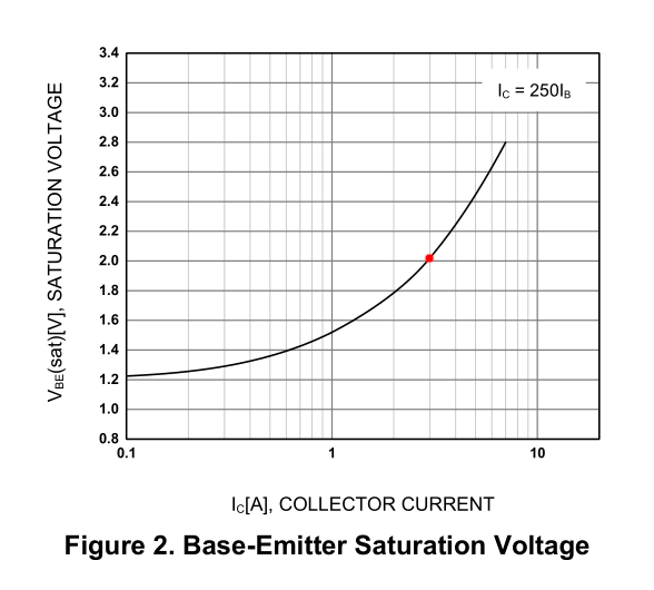
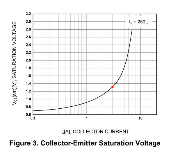
For PWM the transistor is going to be used as a switch, it's either in saturation or cutoff. In the datasheet saturation specifications they are showing the base current as being 1/250th of the collector current, so 12 mA for an IC of 3 A.

Looking at this graph:Vbe(sat) for Ic = 3A

that puts Vbe(sat) at just over 2 V, so subtract that from the voltage out of your Pi and divide by 12 mA to get the resistance for the base resistor.

From this graph:Vce(sat) for Ic = 3A

Vce(sat) is about 1.3 V, so subtract that from the supply voltage to get the voltage available to the LED.

\$\endgroup\$
16
  • 2
    \$\begingroup\$ The Vce(sat) of the darlington is 2.5V max at 3A. Then the "12V" LED gets only 9.5V and might not light or might be very dim. Please post the datasheet for the LED. \$\endgroup\$
    – Audioguru
    Commented Apr 5, 2022 at 0:50
  • 1
    \$\begingroup\$ @Audioguru True, they'd probably be better off with a MOSFET for this application. \$\endgroup\$
    – GodJihyo
    Commented Apr 5, 2022 at 4:02
  • \$\begingroup\$ @Audioguru I do not have a datasheet for the LED, unfortunately. It works by 12V and according to that, I measured a 3A load from my power supply. What if I provide 14.5V to my collector's leg so that I compensate for the 2.5V drop while the saturation? \$\endgroup\$
    – Nihat
    Commented Apr 5, 2022 at 6:38
  • \$\begingroup\$ @GodJihyo may I ask which graph you looked at for the \$V_{BE(SAT)}\$ value? Additionally, is the 12mA value the threshold value for the transistor needed to be exceeded to be able to saturate? \$\endgroup\$
    – Nihat
    Commented Apr 5, 2022 at 6:44
  • 1
    \$\begingroup\$ hFE is used only when a transistor or darlington IS NOT SATURATED. The hFE spec has a fairly high Vce. Most transistors have a maximum Vce saturation voltage when the base current is 1/10th the collector current even if the non-saturated hFE is very high. A darlington has a base current of 1/250th the collector current for its guaranteed max VCE when saturated. \$\endgroup\$
    – Audioguru
    Commented Apr 7, 2022 at 0:17

Your Answer

By clicking “Post Your Answer”, you agree to our terms of service and acknowledge you have read our privacy policy.

Not the answer you're looking for? Browse other questions tagged or ask your own question.