All most of the tutorial talks about MOSFET as a switch. But I want to know about the behavior of P MOSFET. When I apply positive terminal of the supply to the Drain and check the voltage against ground and Drain, it shows the power supply voltage. When I check voltage between Source and Ground, almost same voltage is shown but Drain and Source terminal do not have continuity. I want to know about this phenomenon. I want to use P Mosfet in switching between two power supplies. When power is on I want to power up my Router with normal electrical power and when power is gone it automatically use power from the battery so connected. My actual need is to switch between battery power and Power supply. Any suggestions??
-
\$\begingroup\$ Sounds like the phenomenon is leakage. Semiconductors are not perfect switches. What happens if you put a load on the mosfet? What is the gate connected to? \$\endgroup\$– KartmanCommented Apr 12, 2022 at 2:49
-
\$\begingroup\$ Gate was unconnected. \$\endgroup\$– rs04Commented Apr 12, 2022 at 2:57
-
\$\begingroup\$ If the gate isn't connected, there could still be a voltage on it which will turn the device on or off. Connect gate to source and the FET should turn off. \$\endgroup\$– hacktasticalCommented Apr 12, 2022 at 3:24
-
\$\begingroup\$ FETs conduct rapidly when (Vgs/Vt) >2 due to square law. Can you dissipate the power loss and what is your max current spec.? \$\endgroup\$– D.A.S.Commented Apr 12, 2022 at 4:02
1 Answer
Ignoring the first part of your question, and getting to the meat of it: how to reliably and safely switch from wall power to battery?
There's a few ways:
- (1) Use a diode 'or' circuit. Drawback: not that efficient due to the diode IR drop.
- (2) Use a 'powerpath' IC that does automatic swtchover. Drawback: needs more work
- (3) Use a diode and p-FET. Drawback: care must be taken to prevent back-charging the battery.
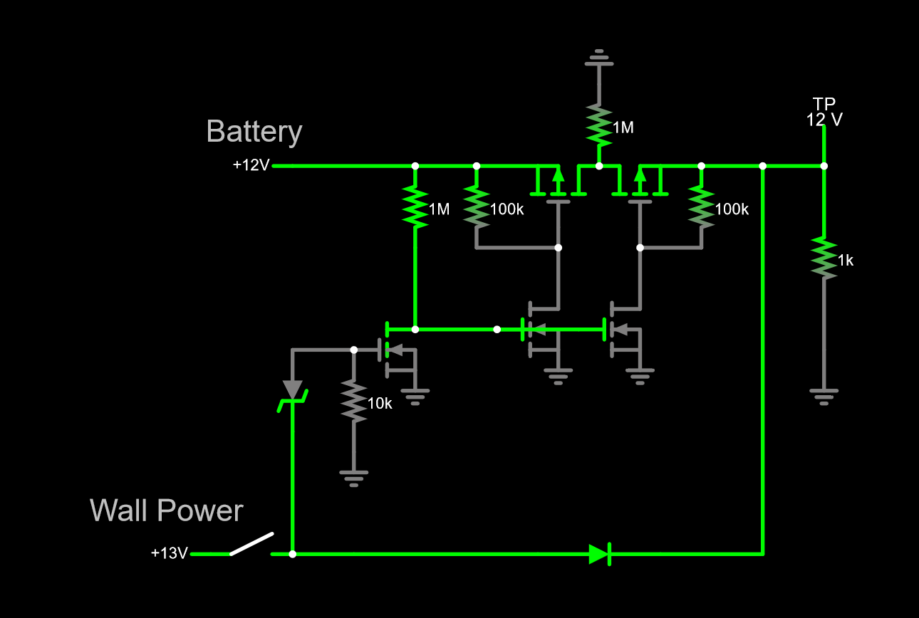
So I've worked up a circuit to do all that in (3), with guards against corner cases, like low low battery and low line-in (simulate it here):
The key point to notice is that I've used 2 p-FETs back-to-back. This accomplishes two goals:
- blocks the body diode
- prevents flow to the battery if its voltage goes low (right FET stays biased off.)
The Zener diode sets the lockout voltage for the wall-power input at about 5.6+1.5 = 7.1V. You can adjust this by adding a voltage divider or changing the Zener to a different breakdown voltage.
Finally, the series diode and p-FETs need to be sized large enough to handle your load current. The n-FETs can be any common switch type like 2N7002 or BSS138.

