I'm designing a PCB which involves integrating two microcontrollers - an ATSAMD51 (Cortex M4)-based Arduino, and a Raspberry Pi.
I need to connect a parallel bus of 10 signals between the two devices. These need to arrive at specific pins of the ATSAMD51 to take advantage of certain ALT_SEL functions it has.
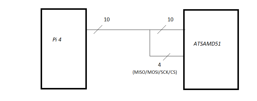
A specific set of the Raspberry Pi pins also correspond to one of its SPI controllers. I've thought ahead to further applications that would be able to reuse these two reprogrammable devices in different ways, and as long as I'm designing a PCB, I'd like to build in a bit of future-proofing if I can. The 4 pins that correspond to the SPI bus on the Arduino are free. It occurred to me that I could fork four of the signals that the Pi could use as SPI, and wire them into the corresponding SERCOM pads of the SAMD51:
In the primary application, SPI is not used, so those four lines will just be default-inputs and this is safe. Future-me would obviously be using MISO as an ATSAMD51 output, which means making sure its other corresponding ALT_SEL pad isn't also a driving output. I could just be super careful with my microcontroller software, but bugs happen... so I'd like to build in some safety if I can.
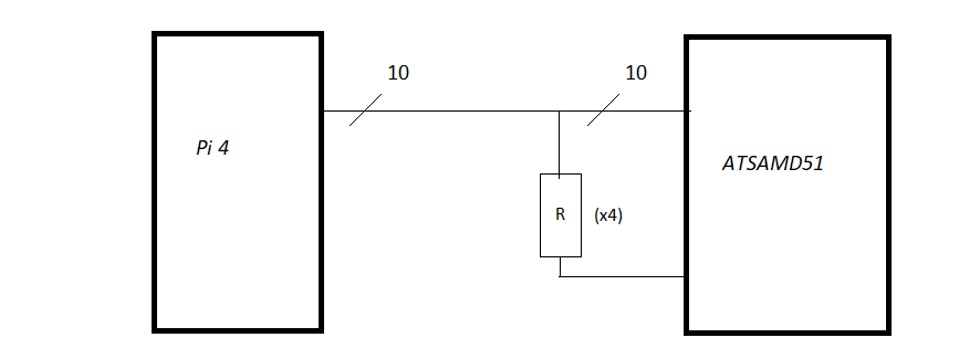
Can I just add resistors in front of the SPI pads? The ATSAMD51 can handle up to 2mA per pin, so worst case, one pad drives HI and one drives LO, and I need to divide 3.3V into 2mA or less. A 2.2 KOhm resistor would ensure these limits are enforced.
I know resistors will add a phase shift, but if they're on all four SPI lines, the SPI bus should remain synchronized. But will this cause other forms of attenuation or concern? Theoretically since it's all GPIO-to-GPIO, the current (and thus the voltage drop) should be fairly minimal. But I don't know what other issues this might cause, or whether this in and of itself may damage the connected devices.
(You may ask why not just use a different Pi SPI controller and run 14 traces; the answer is that I am using a 74CBTLV3861 bidirectional transceiver / bus switch to allow for these devices to be isolated and it has 10 through-lines; the extra 4 traces would mean adding yet another IC, which I'd prefer to avoid.)
Thank you in advance for your help!


