5
\$\begingroup\$

I'm trying to understand how to use a transistor as a switch. I'm sure I am not doing this right.

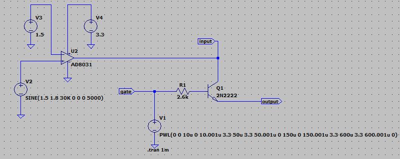
The input signal is a simple 30 kHz square wave, 3.3 V amplitude. There is a second gate signal which is also a square wave with 3.3 V amplitude.

When the gate signal is HIGH (3.3 V), I want it to turn the transistor on and allow the input signal through. When the gate is LOW (0 V), I want it to shut the transistor off and not allow the input signal to pass. Here is my circuit:

enter image description here

The first problem I see is that when the gate signal is HIGH, the output signal is distorted. It seems to spike to 3.3 V, then drop to 2.9 V for the duration of the ON cycle. Then when the gate signal is LOW, the output signal is chattering below zero volts:

enter image description here

I am sure I am misunderstanding how transistors work.

Just a note: When I select the default NPN transistor in LTspice, the circuit works 100% as intended. When I select any other transistor from the 'Pick New Transistor' menu, the circuit malfunctions as described.

\$\endgroup\$
0

3 Answers 3

9
\$\begingroup\$

The “default” LTspice transistor is idealized. Real ones aren’t that good :)

Bipolar transistors are called “switches” but they are not literal switches like a toggle switch is – they are not mechanical contacts.

Perhaps inadvertently, you have set up the transistor as a common-base switch, and that has a chance of working acceptably – you just need some load, the output can’t float.
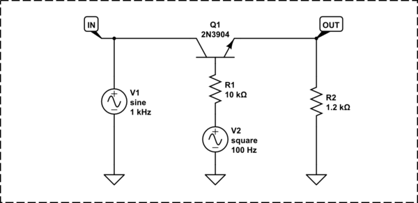
schematic

simulate this circuit – Schematic created using CircuitLab

The component values do depend on the parameters of the transistor, and have to be adjusted in practice. It's not the best way to implement a switch, but it certainly works well enough to be useful for something.

The general idea for common-base switches is having ample amplitude of base drive. Ideally, the base drive would be a current source.

Below are the input, output and control waveforms of the circuit above. The control waveform's amplitude is scaled down 50% to make it fit better in the plot.
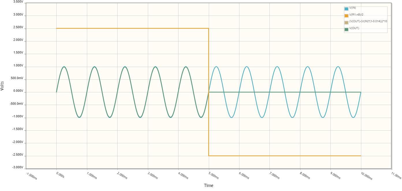
Plot of I/O waveforms, and the control waveform

The non-linear distortion is about 0.5%. The input, output and distortion residue waveforms are plotted below.
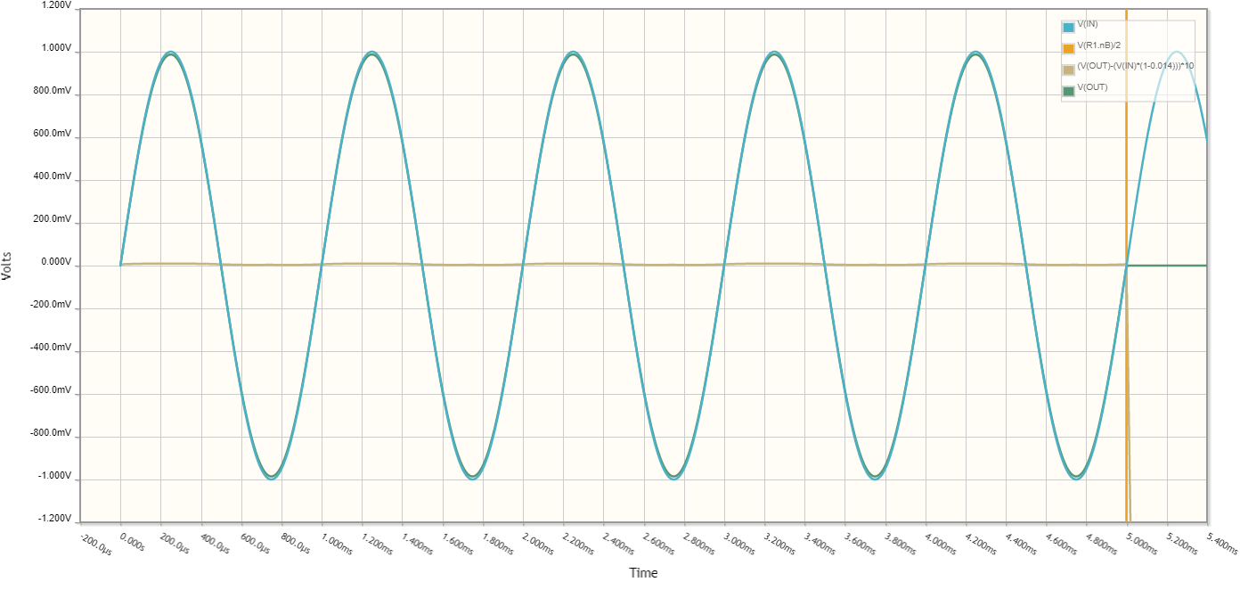
Plot of the I/O waveforms and the distortion residue while the switch is on

The output isolation at 1kHz in the off state is beyond the fidelity of CircuitLab, presumably better than -70dB - this can depend a lot on the transistor used as well.


Another way to achieve a switching action would be to short a high-impedance source.

For example:
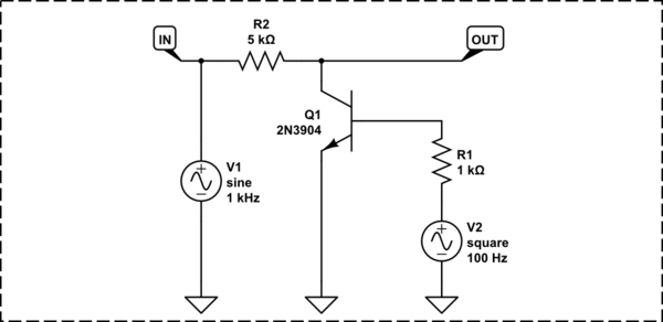
schematic

simulate this circuit

The output swings to 0V when it's turned off:
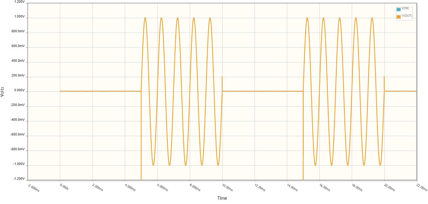
Output waveform of the "shorting" switch

The isolation when OFF is about -66dB, or about 1-in-2000.
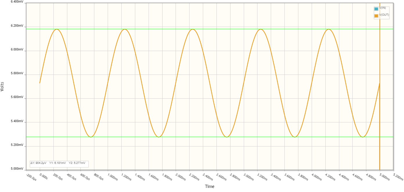
OFF-state output from the switch


A more dependable way to implement a bipolar switch would be to convert the input signal to a current, then switch the current between two resistors, and take the output from one resistor only.
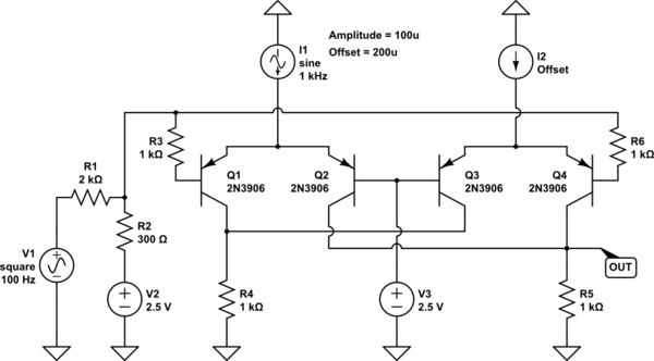
schematic

simulate this circuit

The switching action is clean:

The output voltage waveform as the switch switches

The distortion residuals are <0.1%:

The waveform of distortion residuals


A practical realization of the switch circuit requires a voltage-current converter (V->I), and a source of bias currents, shown below.
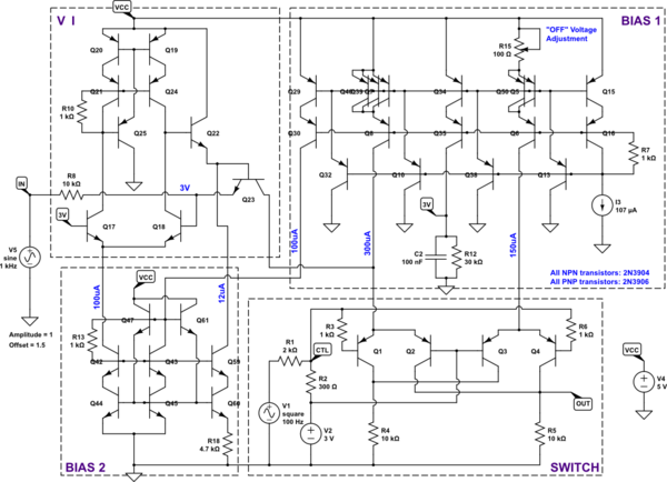
schematic

simulate this circuit

The various currents are derived from a 100uA reference. The current mirror used is an improved 4-transistor Wilson mirror. The additional transistor buffers the base currents and allows paralleling of multiple current output stages in one mirror.

An LM334 could generate the reference cut rent. Another option would be REF200, but it costs an order of magnitude more.

The V->I converter uses a unipolar output op-amp to maintain 3V at the emitter of Q23. R8 loads the input voltage using 3V as the reference, converting it into current. The current passes through Q23.

Perhaps there could be a cascode transistor behind Q23 to increase the accuracy without slowing down the response, but at 5V there’s not much voltage drop to work with – it’d need to be an inverted cascode.

Q23 and the cascode, if any, would benefit from base current compensation, to improve gain accuracy. Q23 could also be a high transconductance low voltage mosfet.

The current then gets subtracted from the 300uA reference, and enters the Q1-Q2 current steering pair. When the switch is turned on, Q2 conducts and passes the current through the output load resistor R5. The current steering could also be done by mosfets, bringing the gain back to 1.000 if combined with a mosfet Q23.

The voltage gain of the switch is about 0.983. Both the input and output impedance are 10 kOhm.

The switching action waveforms are below.
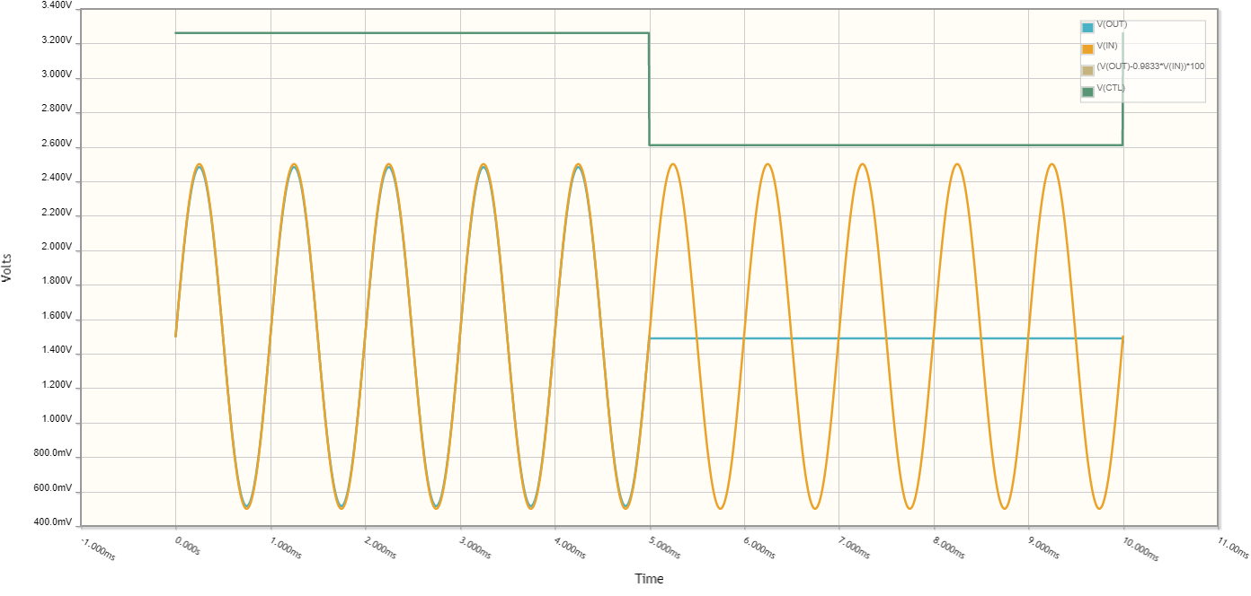
The complete switch's input and output waveforms, and a part of the control waveform

Distortion is under 0.1%. As shown below, it is about 0.06% at 1kHz.
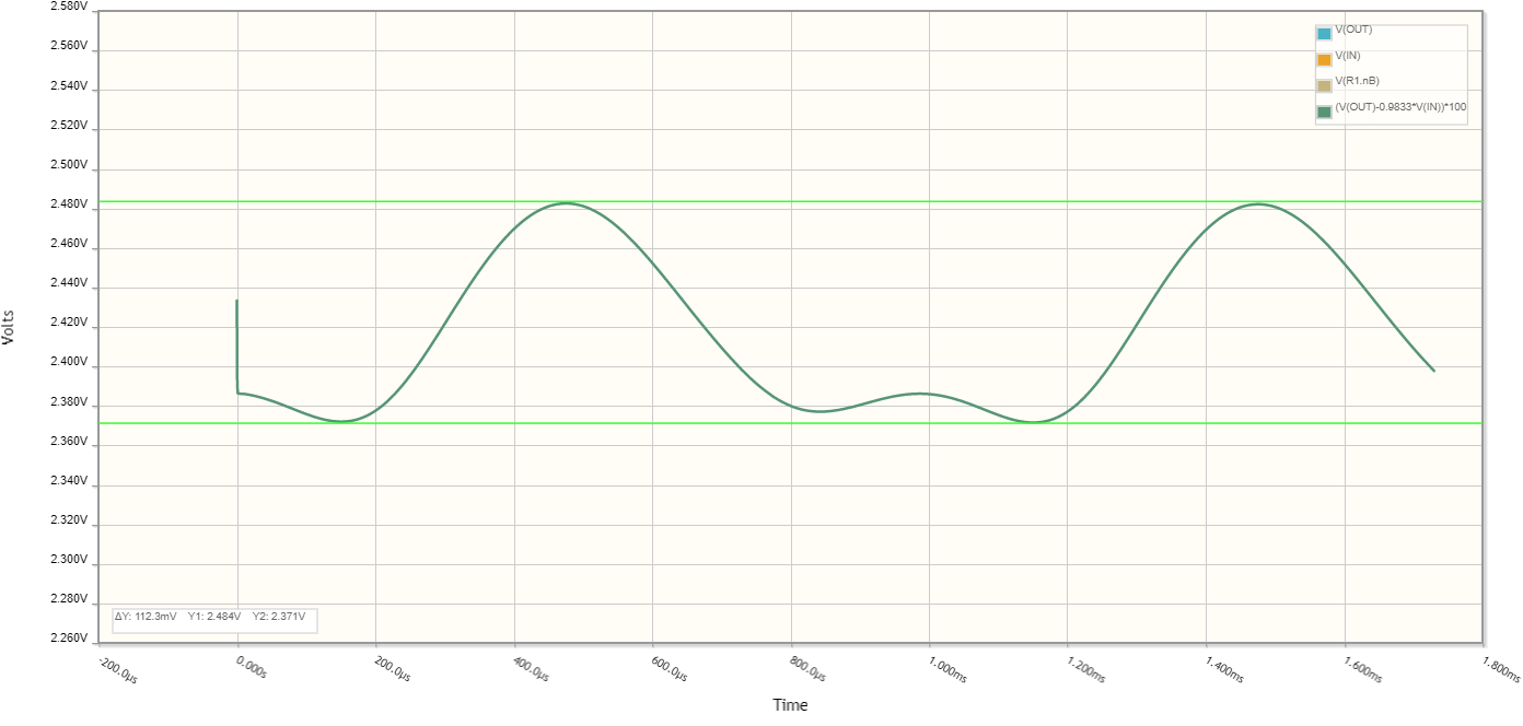
The distortion residual of the complete switch

OFF isolation at 1kHz is -90dB according to CircuitLab. In practice I'd expect -80dB at least with careful layout.

Given the relatively high output impedance, the output would need a buffer stage.

Lower distortion can be achieved by running the switch at a lower gain, say 0.2, and having the buffer stage add the gain back.

The V->I converter could be done with an op-amp Howland current pump, but that would take good resistors and a good op-amp to be better than the discrete circuit. At 30kHz, you'd need an op-amp with GBW to 10MHz to maintain reasonable distortion, if you care about that.

An op-amp could provide the gain and buffering of the switch output, of course.

Getting a transistor acting as a good switch takes a bit of work by the surrounding circuitry :)

\$\endgroup\$
1
  • \$\begingroup\$ Thank you, this was very helpful! \$\endgroup\$
    – Dustin
    Commented Apr 16, 2022 at 19:22
3
\$\begingroup\$

The idea that transistors behave as switches is extremely misleading. Yes, they can be turned 'on' and 'off' for digital circuits, but this is completely different than a mechanical switch as Kuba pointed out. The closest thing to a mechanical switch using transistors is called a pass-gate.

Always remember:

  • P-type transistors (such as PNP or pMOS) source current.
  • N-type transistors (such as NPN or nMOS) sink current.

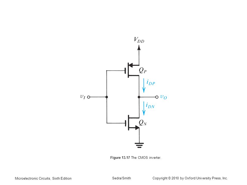
In the circuit below QN is an nMOS transistor, while QP is a pMOS transistor. QP can be used to 'send' current from power (VDD) to vo, while QN can be used to 'receive' current from vo to ground. Each transistor current in this circuit is primarily controlled its respective gate-to-source voltage.

1

(Image source: Microelectronic Circuits, Sixth Edition by Sedra & Smith, Figure 13.17 The CMOS Inverter - as included in previous question: CMOS Inverter-based question from Sedra&Smith, Microelectronic Circuits, Author - MaxFrost)

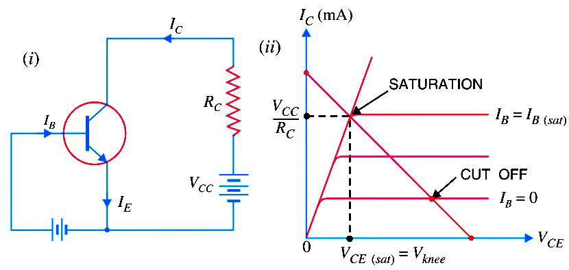
You may have also heard that transistors also behave as 'amplifiers'. This is also true. As you continue to learn about transistors, you'll find they operate in one of three regions (depending on the voltages at the gate, source and drain):

  • Cutoff (or simply off)
  • Triode (or simply on)
  • Saturation (or activation)

Triode and Cutoff are primarily used in digital circuits, while the saturation region is used in analog circuits.

2

(Image source: Inst Tools - Transistor Cut off, Saturation & Active Regions)

\$\endgroup\$
3
  • 3
    \$\begingroup\$ Jacob - Welcome :-) Thanks for adding an answer. I see you have been on Stack Overflow already. When you have time, although it's very similar to SO, I recommend you check out our tour and help center e.g. explaining the required reference links for any resources (e.g. text, images, photos etc.) when you include any in your posts. In order to help, I've found and added the required links this time (if you have a different legitimate link for the Sedra & Smith diagram, feel free to change the one that I found, if you prefer). Thanks again. \$\endgroup\$
    – SamGibson
    Commented Apr 16, 2022 at 19:57
  • \$\begingroup\$ Except that sometimes NMOS transistors can source current and sometimes PMOS transistors can sink current. Otherwise, Intel would not have been able to construct the 8086 using only NMOS transistors. Also, I think switching from MOSFETs to BJTs midanswer is confusing, particularly because the term saturation has vastly different meanings depending on context. \$\endgroup\$ Commented Apr 19, 2022 at 18:24
  • \$\begingroup\$ Using an pMOS as an active load is not the same thing as being a current sink. Anybody trying to learn how to design transistor circuits is going to get very confused very quickly if they focus on niche applications. When talking about the operating region of a transistor, "saturation" is not an ambiguous. \$\endgroup\$
    – Jacob
    Commented Apr 19, 2022 at 18:45
1
\$\begingroup\$

It won't work particularly well with an NPN, but you do need a pulldown resistor on the output -- perhaps 1kΩ. With that, the gate signal will still feed through the base of the NPN -- better to increase the 2.2k to over 10 kΩ to minimize this.

\$\endgroup\$

Your Answer

By clicking “Post Your Answer”, you agree to our terms of service and acknowledge you have read our privacy policy.

Not the answer you're looking for? Browse other questions tagged or ask your own question.