2
\$\begingroup\$

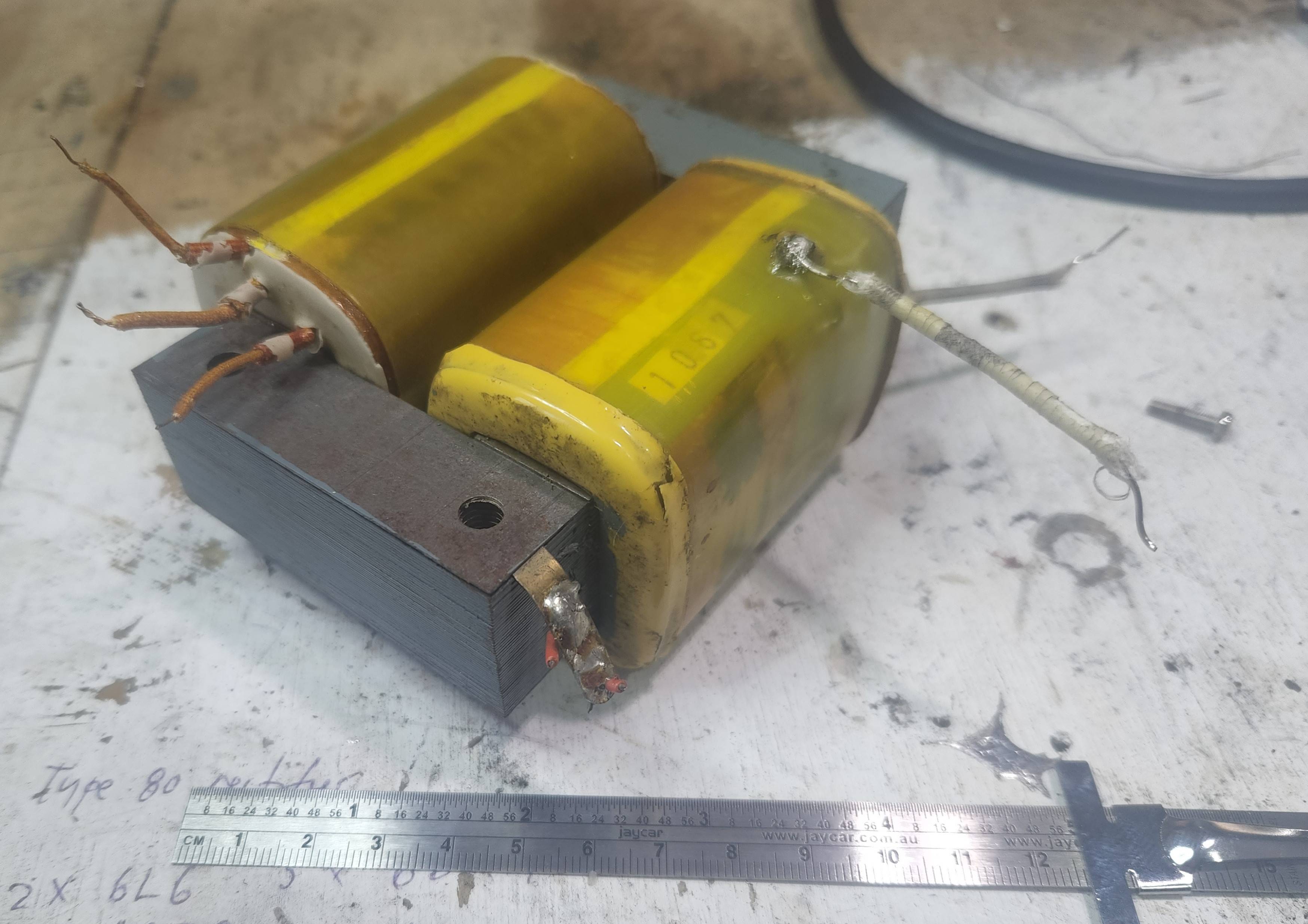
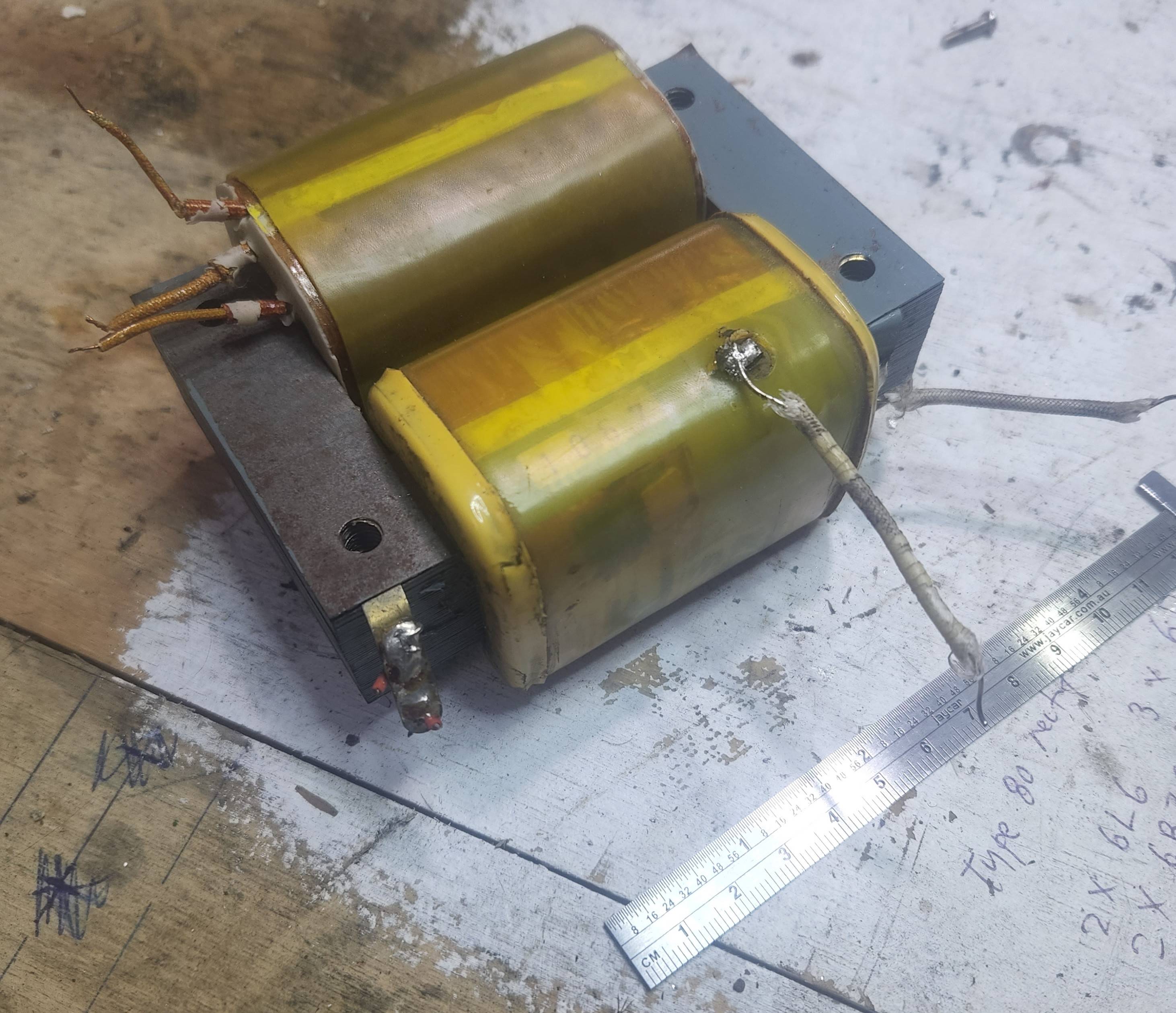
I am in possession of a collection of salvaged transformers. I am curious about this one in particular:

enter image description here

enter image description here

I gather from its laminated core that it is intended for use at line frequency.

What I assume to be the primary winding is centre-tapped; each half of the winding has a DC resistance of about 7R.

The secondary winding has a DC resistance in the tens of kiloohms.

I put 10VAC at 50Hz across the full primary winding and measured over 260V on the secondary.

Call it an academic exercise; how could one go about safely estimating the output winding's maximum design current?

The windings are inaccessible behind much plastic wrapping so I can't measure the wire diameter.

I can measure the diameter of the primary winding which might give some indication.

Is heating of the transformer under load the most obvious indicator of overcurrent [or over-power?] and if yes, what increase in temperature should sensibly be considered excessive?

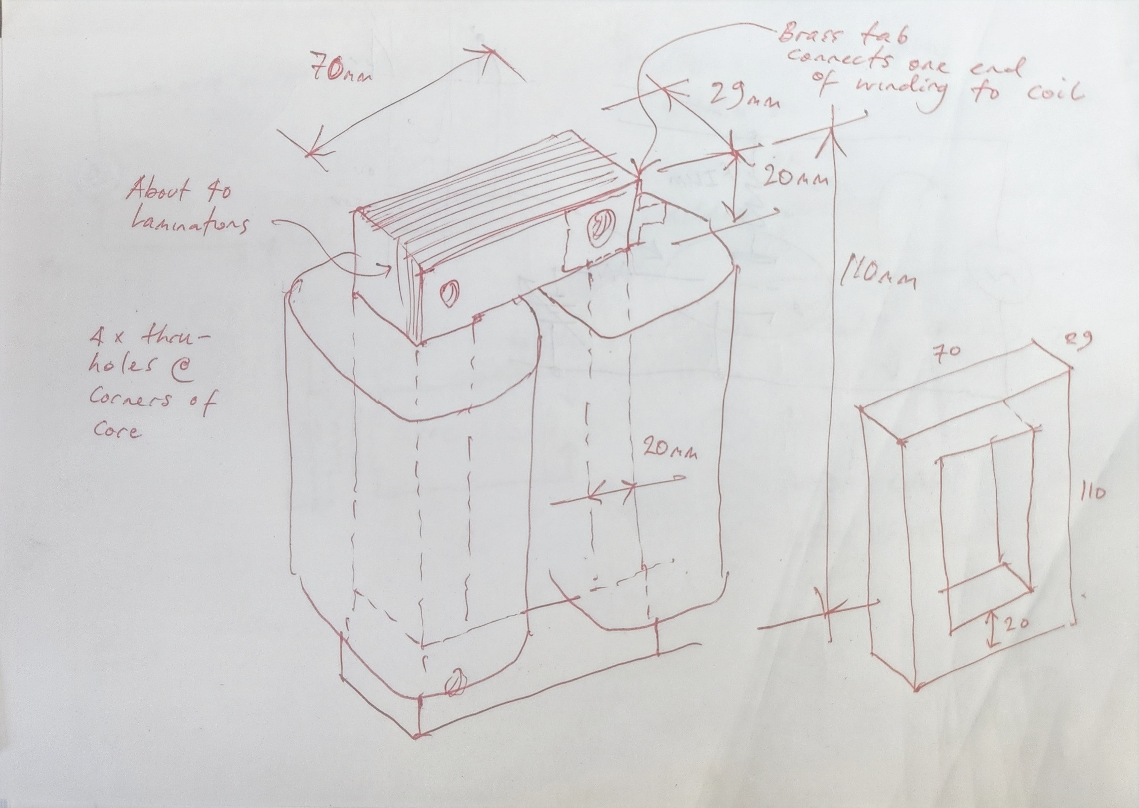
The dimensions of the core are:

Overall 110mm high, 70mm wide, 29mm thick, made up of about 40 laminations.

enter image description here

I was setting up to make some measurements and calculate rise in temperature when I noticed an unexpectedly low secondary voltage when loaded. I tried multiples and fractions of the load and the relationship between load and voltage seemed to be linear - as though the secondary's current were somehow fixed.

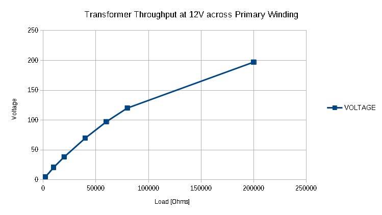
However testing with more values showed that perhaps this transformer is intended to provide very little current indeed:

enter image description here

With 12VAC across the primary, the secondary open circuit voltage is 324V.

Providing about 1mA into a 200k load this drops to just shy of 200V; into A 10K load we get just over 20V for 2mA.

It occurs to me that the graphed curve looks to be flattening, and that at some load range in the many hundreds of kOhms the output voltage should remain reasonably constant.

The question that comes to mind now is - and it's purely out of interest - what might the original purpose of this transformer have been? Its power seems quite low [per kilogram, just intuitively]. The step-up ratio is staggering; I have a hunch this was salvaged from some kind of electronic test equipment. Perhaps something to do with a CRT?

\$\endgroup\$
3
  • \$\begingroup\$ If it gets too hot to touch that enough. I would expect perhaps 10VA / kg \$\endgroup\$
    – D.A.S.
    Commented May 3, 2022 at 5:09
  • \$\begingroup\$ Can you put some dimensional info about the core? And also, are you sure about which side is primary? \$\endgroup\$ Commented May 3, 2022 at 5:49
  • \$\begingroup\$ Isn't the primary winding a matter of how the transformer is used? I.e. if I excite one winding and then use the power from the second winding 'downstream' haven't I told the transformer which side is the primary side [Honest question]? \$\endgroup\$
    – Simon Owen
    Commented May 3, 2022 at 12:46

1 Answer 1

2
\$\begingroup\$

It sounds like you already have the windings identified. For other readers I'll give a tip. When measuring an unidentified transformer, always apply your excitation to the highest resistance winding. This is likely to be the highest turns winding, so all coil voltages will then be below your excitation voltage.

Over-current will heat the transformer.

The sensitive parts of the transformer are the enamel insulation on the wire, and any paper or plastic foils used to separate layers in the windings. As it's an unidentifiable transformer, you don't know what these materials are, so you'll have to play safe.

There are several failure modes. The prompt one of emitting smoke and fire, and loss of strength of any plastics used in construction. You have to get very hot for these. There's a long term one of insulation degradation over thousands of hours leading to eventual voltage breakdown of the insulation. That occurs at much lower temperatures.

Fortunately the loss dissipation of the copper goes as the current squared, whereas the output VA goes as the current. This means that you can afford to be quite conservative on winding temperature without it costing you too much on VA throughput.

Measuring the temperature of the transformer as a whole takes a long time, for it to come to thermal equilibrium, and is tricky, needing good contact to the surface, and is inaccurate, as the surface is cooler than the windings.

Measuring the temperature of the windings themselves can be a little faster and a lot more accurate, using the tempco of copper itself as the thermometer. Copper, in common with most pure metals, has a tempco of about 0.4%/C, or 10% in 25C. Measure the winding resistance. Run the transformer at a test current for a while, then disconnect it and remeasure the resistance. Rinse and repeat while drawing a graph, until you have a good idea of where the graph is headed, or until the graph is stable.

How hot should you allow it to get? I don't like a surface temperature higher than 60 C, especially on a rescue transformer, but then I'm a wimp (60 C is the temperature at which you can touch something with a dry hand, but not hold contact for more than a few seconds). Given that I see figures as low as 105 C given in the temperature specifications for some 'high temperature' insulation materials, I would say that is an absolute upper limit for an unknown transformer, and ideally you would use somewhat less.

Remember that transformer losses give you a temperature rise, not an absolute temperature. Do these experiments in a representative ambient, and allow for the expected worst case ambient temperature rise.

\$\endgroup\$
1
  • \$\begingroup\$ That's my evening sorted then! \$\endgroup\$
    – Simon Owen
    Commented May 3, 2022 at 7:16

Your Answer

By clicking “Post Your Answer”, you agree to our terms of service and acknowledge you have read our privacy policy.

Not the answer you're looking for? Browse other questions tagged or ask your own question.