1
\$\begingroup\$

I am interested in how you would approach finding the transfer function of a circuit that involves a linear transformer. For example, the circuit below

schematic

simulate this circuit – Schematic created using CircuitLab

If I wanted to find the transfer function of $$ \frac{Vout}{Vin}$$

I would first combine the RHS of the circuit, C1, C2 and R2 into an equivalent impedance. However, I'm not sure if I should use S-domain or Phasor as the source is AC 120RMS.

Then, assuming the transformer as a gain of 1, the mutual inductance would be: $$ M = 1*\sqrt{L1*L2} = 0.01 $$

From here I'm not quite sure what to do. I know the mutual inductance would create a induced voltage on each side of the transformer but I am unsure how to determine this (or use it in circuit analysis)

Note this is a circuit I made up so apologies if the values don't make sense or resemble anything that would occur in real life. I am just trying to understand how to tackle a transfer function problem that involves a ideal transformer.

\$\endgroup\$
6
  • 3
    \$\begingroup\$ That’s not a transformer but two separate inductors. \$\endgroup\$
    – winny
    Commented May 8, 2022 at 12:39
  • \$\begingroup\$ winny is correct the primary windings from the secondary windings are isolated from each other. \$\endgroup\$
    – Jun Seo-He
    Commented May 8, 2022 at 12:41
  • \$\begingroup\$ @JunSeo-He In a real transformer yes, but what OP has drawn is not a transformer. \$\endgroup\$
    – winny
    Commented May 8, 2022 at 12:47
  • \$\begingroup\$ winny I agree with you .The OP has drawn 2 seperated inductors which are coupled to each other but they are not a transformer. \$\endgroup\$
    – Jun Seo-He
    Commented May 8, 2022 at 12:51
  • \$\begingroup\$ @JunSeo-He No, there is no indication of coupling. Isolation does not define a transformer, it's just something transformers are commonly used for. \$\endgroup\$
    – Hearth
    Commented May 8, 2022 at 15:45

4 Answers 4

1
\$\begingroup\$
  • The current and impedance of each winding are the same for N=1 thus the transfer function for differential voltage is unchanged. However transformers and all coils have an inherent self-capacitance from interwinding proximity and coupling between each winding and capacitance in the cores. There can also be magnetic eddy current effects in the core that are more lossy than the conductors. The net effects of this makes most transformers very limited in bandwidth (typically 2 to 3 decays) where the operation is linear in losses.

The impedances of this balanced transformer depends on the polarity of each winding.. When polarity is on the same side the differential inductance cancels out for the limited BW of the transformer. Wire pairs also have distributed inductance per unit length and mutual coupling but the precision of balancing is far less than the CMRR of an INstrument Amplifier.

The other transfer function is due to external common mode (CM) excitation, which due to M and differential L defines the mechanism for Common Mode Rejection Ratio or simply, attenuation vs frequency. 100 dB CMRR requires a balance error of 0.001%

Conclusion

The differential transfer function might be x1 for N=1 in the linear range of the transformer, but other factors to consider are the hysteresis, frequency and excitation voltage across the coil.

The common-mode transfer function depends on impedance ratio and balance error.

\$\endgroup\$
1
\$\begingroup\$

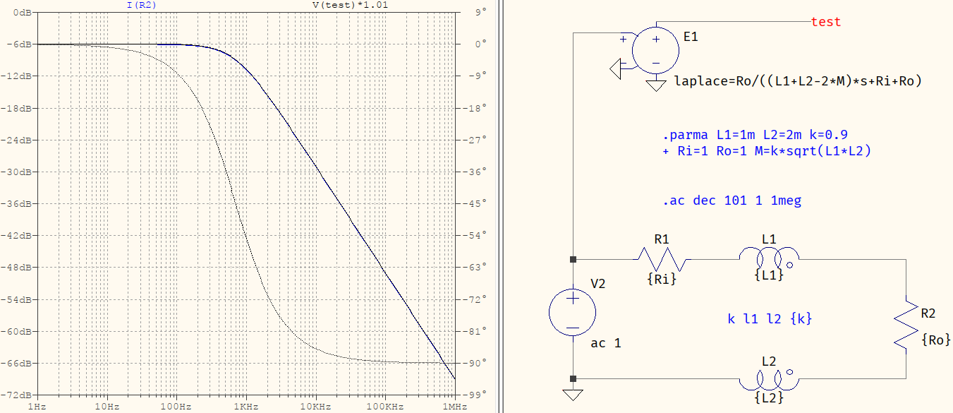
You can approach it just like any other circuit: form the system of equations and solve it. Suppose you reduce it to the simple case of a source (V2) with a series resistance (R1), the coupled inductors (L1 and L2), and a load (R2):

test

Then, the circuit has only one loop and there will be only one current, for which the following can be written:

$$\begin{align} V_{in}&=R_1I+sI(L_1-M)+R_2I+sI(L_2-M) \tag{1} \\ \Rightarrow I&=\dfrac{V_{in}}{(L_1+L_2-2M)s+R_1+R_2} \tag{2} \\ \Rightarrow \dfrac{V_{out}}{R_2}&=\dfrac{V_{in}}{(L_1+L_2-2M)s+R_1+R_2} \\ \Rightarrow \dfrac{V_{out}}{V_{in}}&=\dfrac{R_2}{(L_1+L_2-2M)s+R_1+R_2} \tag{3} \end{align}$$

Sure enough, as you can see in the picture above, the transfer function corresponds with the current through R2 (since R2=1 the voltage is the same). I've also used different values for inductors to avoid the particular case of M=k*L. The only thing I had to do to avoid a complete overlap of the traces was to add a slight multiplication to one of the traces, to stand out. The phases do overlap, though, since the multiplication of the magnitude doesn't influence it.

From this point, on, you can build upon it to reach your case.

\$\endgroup\$
0
\$\begingroup\$

As pointed @Tony Stewart EE75 in his answer,
here is (example: variable frequency) what can happen ("ideal" transformer) in that circuit.
enter image description here So, if you want a "transfer function" @50 Hz, be sure to have a "good" model.

\$\endgroup\$
0
\$\begingroup\$

Vout/Vin or equally Vsec/Vprim = Nsec/Nprim.

\$\endgroup\$

Your Answer

By clicking “Post Your Answer”, you agree to our terms of service and acknowledge you have read our privacy policy.

Not the answer you're looking for? Browse other questions tagged or ask your own question.