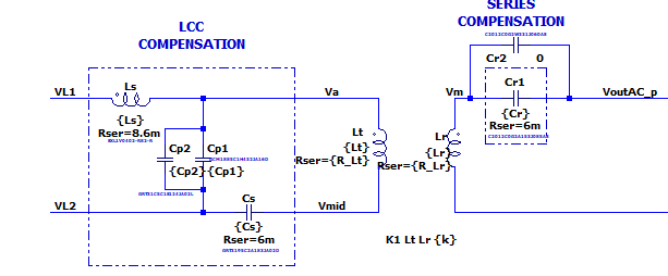
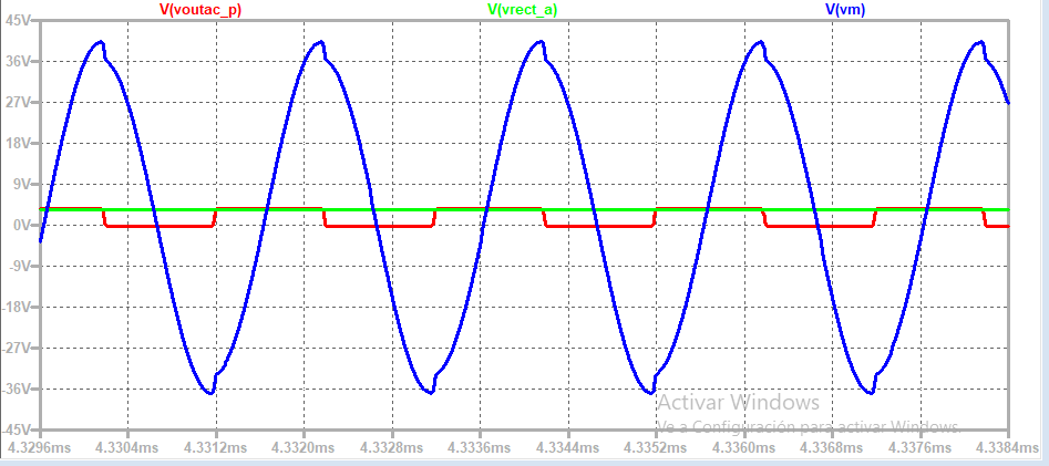
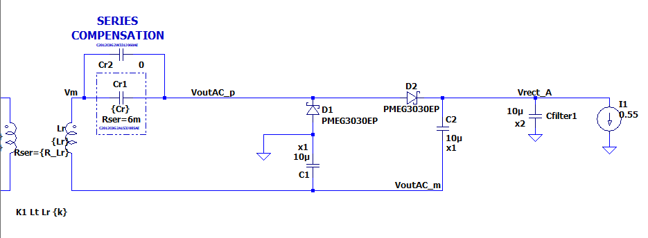
I need some help with this schematic to have higher voltage at Vrect. This is for charging a receiver at 25 mm in a WPT application. I was expecting a voltage of 2Vin at the output of the voltage doubler, but as shown in the simulation, is not working. I'm using inductive coupling to transmit energy  Something wrong is happening and I don't know what


\$\begingroup\$
\$\endgroup\$
6
1 Answer
\$\begingroup\$
\$\endgroup\$
1
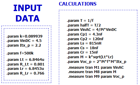
The coupling between the two coils is very small. 0.089939 means about only ~9% of the flux from the primary coil is making it to the secondary. Try starting with a K = 1 for an ideal transformer to get things working.
-
\$\begingroup\$ The thing is that the coils are already designed for that coupling factor. I don't have a transformer, I have PCB coils simulated with Ansys, trying to build optimum coils in a limited area \$\endgroup\$ Commented May 18, 2022 at 8:14

15nand5u, formed byC1andC2in series). Not lastly, have you considered that 0.55 A is too much for the doubler? (don't forget to add theloadflag to the current source, otherwise it will sink current even when the voltage goes negative) \$\endgroup\$