2
\$\begingroup\$

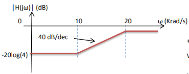
I am trying to design an active filter, which I assume is an active high pass filter according to what I see from the Bode plot.

I can get the transfer function from this plot and then I need to design an active filter .

The transfer function given:

enter image description here

enter image description here

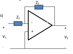
I need to design something like this:

enter image description here

\$\endgroup\$
5
  • 2
    \$\begingroup\$ I would first rewrite the transfer function to highlight a dc gain \$G_0\$: divide all the numerator \$N\$ terms by 100 and all the denominator \$D\$ by 400. Then re-arrange the expression in the form of \$G(s)=G_0\frac{1+\frac{s}{\omega_{0N}Q_N}+(\frac{s}{\omega_{0N}})^2}{1+\frac{s}{\omega_{0}Q}+(\frac{s}{\omega_{0}})^2}\$. \$\endgroup\$ Commented May 22, 2022 at 6:14
  • 1
    \$\begingroup\$ Do you see the DC gain of 1/4 and HF gain of 1/2? \$\endgroup\$
    – D.A.S.
    Commented May 22, 2022 at 6:15
  • 1
    \$\begingroup\$ \$\omega_{_0}=20\$ and \$\zeta=1\$ and the transfer function is \$1\cdot\frac{s^2}{s^2+2\zeta\omega_{_0} s+\omega_{_0}^2}+\frac12\cdot\frac{2\zeta\omega_{_0} s}{s^2+2\zeta\omega_{_0} s+\omega_{_0}^2}+\frac14\cdot\frac{\omega_{_0}^2}{s^2+2\zeta\omega_{_0} s+\omega_{_0}^2}\$ \$\endgroup\$
    – jonk
    Commented May 22, 2022 at 6:24
  • \$\begingroup\$ and the topology for those equations is? verbal? j@onk? \$\endgroup\$
    – D.A.S.
    Commented May 22, 2022 at 7:28
  • \$\begingroup\$ Thank You guys so much for the help. This seem like different ways to write the transfer function. It is indeed a different useful pov \$\endgroup\$ Commented May 24, 2022 at 4:12

3 Answers 3

3
\$\begingroup\$

When I made errors in my assumptions for specs. My choice words fit, there is no significant change in the 2nd order equation simplifying it to a 1st order equation. s^2 factors cancel out when the roots of the first order are only an octave apart. There is no significant change or benefit.

Hence @Antonio51 is 100% right.

Doing a sensitivity analysis with the derivative of H(s) proves that.

mY error: fmax is H(s)=0 dB with breakpoints 1 octave apart and 12dB space can never achieve 40 dB/dec or 12 dB/octave and almost 4dB /octave. where 3 dB/octave is used for Pink noise filters.

From the symmetry of this question, there is a simple passive approach.

Rule of Thumb.

The more mistakes you correct, the more careful you try to be in making fast assumptions. But then you don't have to be brilliant ("I arn't") just work harder to correct them and gain more experience. Most of my Analog/ SCADA experience was my 1st 5 years in Aerospace 40 years ago. NEVER ASSUME ANY DESIGN IMPLEMENTATION SPECIFICS before you identify the key measurable design specs. (remember there is a U between "ass and me" if I tell you to use this when you know there is a better way.

Write Specs, then solve

  • This is #1 cause of design failures by EE/ESE/ECE students who graduate, even the best students. If you find yourself thinking, how can we do this with a ? before you document a well-defined problem. i.e. write a design list of specs 1st. Then break it down into functions with I/O parameters & tolerances. Then start the 2nd stage, the realization part of the design. 3rd stage is verify.
  • Write measurable design specs 1st then design to meet or exceed.

There must be some shunt attenuation for partial gains. This is also called a Lead-Lag attenuator and is common for PLL compensation loops as it adds +ve phase margin to the loop when used near unity gain. However, there the breakpoints are better selected one decade (10:1) apart and not just 1 octave apart (2:1) which is only 12 dB difference between a gain of 0.25 and 0.25. and over a much wider span 12 dB/octave.

Thus you never achieve 12 dB/octave because of the -3dB breakpoints typically select for the half-power bandwidth. So it is only 6dB/octave unless you raise the Q for more phase shift (which is not needed here) So you might assume maximally flat Butterworth or something else as long as you define that assumption not given.

While we're at it, since there is no gain, we might as well consider a passive filter with say 1k to 10k input impedance.

Disregard unless to consider a different problem

Specs

DC gain = 0.25 (~-12 dB = -20 log(4)) 2nd order ramp up at 10 rad/s HF gain = 0.5 (~-6 dB) 2nd order ramp to flat at 20 rad/s

  • 2nd order equation implies THERE MUST BE TWO REACTIVE ELEMENTS minimum.

  • The Breakpoints and BW are defined by the "half-power point" ~ -3dB so each point reduces the slope from 2nd order 12 dB/octave to only 6 dB actual at each breakpoint -12,-6 dB and "appears like a 1st order filter" yes is a 2nd order filter. It isn't because the asymptotes are too close together and thus interact with each other. Inverting / Normal (optional) Lead-lag phase frequency response with 6 dB dirfference ramp up from asymptotes 10 to 20 rad/s This can be done with Resistor ratios or Capacitor ratios but in this case as a lead-lag filter or flat with a HP then LP in between.
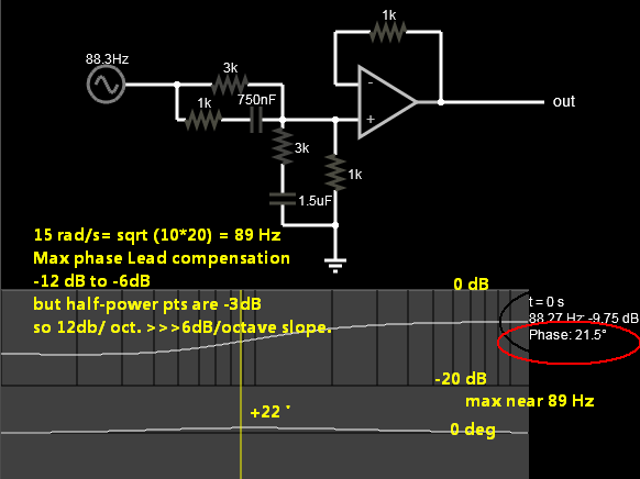
enter image description here

  1. direct R path 3k:1k satisfies the -12 dB LF 1st breakpoint
  2. AC path 1k:3k > R1//R2=Req satisfies the 2k:2k -6 dB HF 2nd point
  3. The centre frequency will be the RMS product of each breakpoint 10, 20 rad/s= 14.14 rad/s = 89 Hz
  4. Verify the max Phase lead-lag compensation circuit is maximum at 89 Hz with 5% parts.

All the boxes are checked. Design complete.

However , your Prof may expect you to do it the hard way the 1st time.

Opinion

My simple approach only used a few minutes to create with experience and >30 minutes to write this up. You will be able to do this later too.

With experience, Feinmann could do this in his head.

\$\endgroup\$
4
  • 1
    \$\begingroup\$ Hi Tony, from the given transfer function, the asymptotic high-frequency gain is 0 dB while the dc gain is -12 dB. Where do you get your -6 dB? \$\endgroup\$ Commented May 22, 2022 at 15:14
  • \$\begingroup\$ oops seniors moment... must have been that inaccurate plot \$\endgroup\$
    – D.A.S.
    Commented May 22, 2022 at 15:20
  • 1
    \$\begingroup\$ No problem : ) The plot is wrong ac-magnitude wise. So we have two coincident zeroes at 1.592 Hz, two coincident poles at 3.183 Hz and a dc gain of 0.25. \$\endgroup\$ Commented May 22, 2022 at 15:25
  • \$\begingroup\$ How can I convert it into an inverting amplifier? \$\endgroup\$ Commented May 27, 2022 at 23:23
3
\$\begingroup\$

UPDATE: I made confusion with the OP function between omega and frequency:
As the function in the "picture" is not related to the specification itself.
I used the idea of @Tony Stewart EE75, thanks ...

Here is a simulation that can "answer" the OP question. Idea is ok, but values of components must be updated. Will do later.

It can also be "synthesized" with "one-order" function (numerator and denominator).

enter image description here

Update: corrected f -> omega. Transfer functions not calculated, only adjusted by hand with microcap v12 tools.

enter image description here

\$\endgroup\$
13
  • 1
    \$\begingroup\$ In this picture you can see the OP's transfer function displayed in green. In blue (mostly covered up by red), is the transfer function I computed assuming an ideal opamp and using your circuit elements. Covering over most of it, is red, which is a non-ideal LT1800 opamp with your circuit components applied to it. Not the same. And the transition slope is different, as is the high-pass final voltage gain. \$\endgroup\$
    – jonk
    Commented May 22, 2022 at 23:04
  • 1
    \$\begingroup\$ Ok ... I made a "little error" on the OP function labeled as "omega" and not "frequency" :-( So it is correct. And I did not search the full transfer function of the two circuits I added Only simulated and adjusted by "hand"... You are right. Thanks. \$\endgroup\$
    – Antonio51
    Commented May 23, 2022 at 6:01
  • 1
    \$\begingroup\$ Fast way. The values of 2 resistors (R5/R1=1/4 or R6/R7=1/4 equals DC gain) is obvious. In the case of the function transfer asked, C3 is also quasi obvious. R2=R4=1k (not too low) chosen because high frequency gain = 1 (C1 and C2 are "short"). Then C1 and C2 are chosen (1uF, "high" value because "transition" frequency is "low" - w =10->20) because of the ability of "microcap v12", in real time, to change value of component and showing results on 'AC function' only by pointing component and keying up and down arrows (just choose C1 C2 to some values, ex 1uF and then "point and modify" ...) \$\endgroup\$
    – Antonio51
    Commented May 24, 2022 at 7:47
  • 1
    \$\begingroup\$ This is done when "topology" is "known" ... \$\endgroup\$
    – Antonio51
    Commented May 24, 2022 at 7:48
  • 1
    \$\begingroup\$ After the "picture" is what you wanted, you can then search the "transfer function" ("long" mathematical way...) and make the choice of components more "consistent" and "serious". \$\endgroup\$
    – Antonio51
    Commented May 24, 2022 at 7:53
3
\$\begingroup\$

In my opinion, it is important to explain how to derive an equivalent transfer function from the starting expression. First off, it has to be shaped in a low-entropy form where gain, poles and zeros appear. The normalized polynomial for a second-order expression is \$D(s)=1+\frac{s}{\omega_0Q}+(\frac{s}{\omega_0})^2\$. From there, you must rearrange the numerator and the denominator to approach this format: divide all the numerator terms by 100 and all denominator terms by 400. This gives you a leading term, call it \$G_0\$, which is a dc gain, the value taken by the transfer function when \$s=0\$. It amounts to 0.25 or -12 dB in this case.

Once there, you can identify the resonant frequencies in the numerator and the denominator as well as their respective quality factors \$Q\$. In this example, the resonant frequency in the numerator is 10 rad/s while it is 20 rad/s in the denominator. In this particular example, a quality coefficient of 0.5 signals that the poles or the zeroes are coincident meaning that the numerator can be expressed as \$N(s)=(1+\frac{s}{\omega_z})^2\$ while the denominator is \$D(s)=(1+\frac{s}{\omega_p})^2\$. Finally, the complete transfer function becomes \$G(s)=G_0\frac{(1+\frac{s}{\omega_z})^2}{(1+\frac{s}{\omega_p})^2}\$. A few lines in Mathcad confirm this approach:

enter image description here

This is it for the poles-zeroes location and you now can concentrate on the practical realization of this filter.

\$\endgroup\$
2
  • \$\begingroup\$ This expression adjusts perfectly to the transfer function. With this approach I can see what is Q, the frequency and the Gain of the function. The next step would be to find some kind of Active filter topology that simulates this transfer function, in order to get to this point I need to find the impedance values of this Active Filter. Is there some kind of mathematical approach or do I need to assume a specific topology? \$\endgroup\$ Commented May 27, 2022 at 0:48
  • \$\begingroup\$ @JingHaoSiet, that is the difficulty with this transfer function, you need a pair of coincident zeroes appearing before a pair of coincident poles. I've check the S&K paper kindly recommended by jonk but none of the proposed configurations did the job. Same for the configuration proposed by Antonio51 but the TF I derived leads to a dead-end. What is the purpose of this expression? \$\endgroup\$ Commented May 27, 2022 at 6:44

Your Answer

By clicking “Post Your Answer”, you agree to our terms of service and acknowledge you have read our privacy policy.

Not the answer you're looking for? Browse other questions tagged or ask your own question.